Chapter 3 Installing the Router
Power Connections
Wiring Procedure for DC Input
To connect the router to a DC power source, perform this procedure:
Step 1 Remove power from the DC circuit. To ensure that power is removed from the DC circuit, locate the circuit breaker for the DC circuit, switch the circuit breaker to the OFF position, and tape the
Warning Before performing any of the following procedures, ensure that power is removed from the DC circuit.
Statement 1003
Tip Secure all power cabling when installing this unit to avoid disturbing
Step 2 Strip the wires to the appropriate length for the terminal block on the power supply.
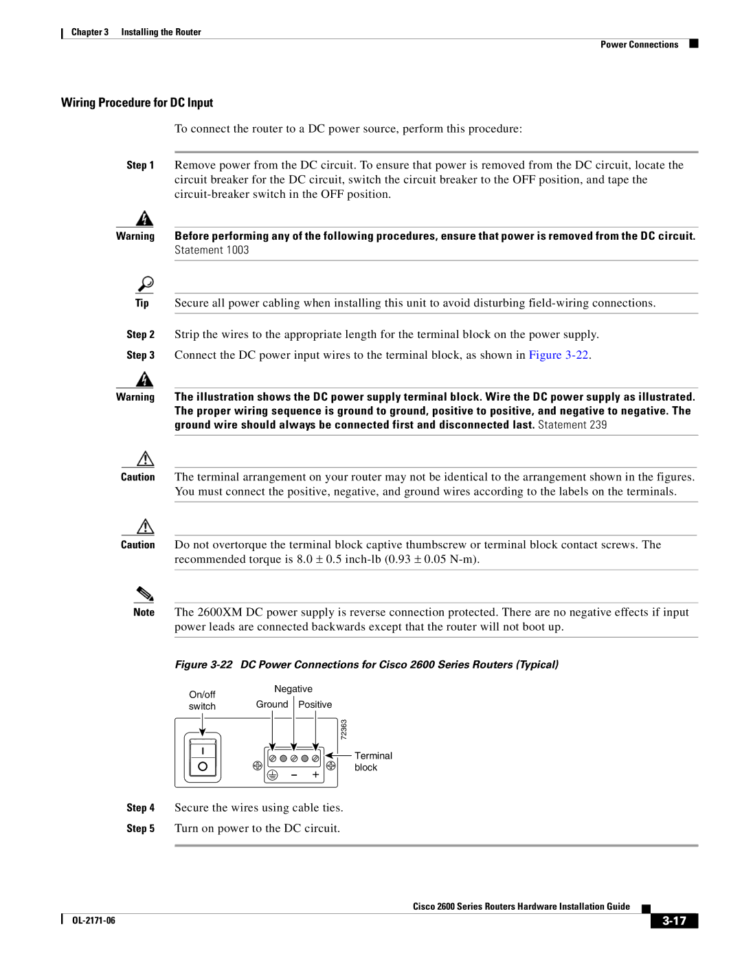
Step 3 Connect the DC power input wires to the terminal block, as shown in Figure
Warning The illustration shows the DC power supply terminal block. Wire the DC power supply as illustrated. The proper wiring sequence is ground to ground, positive to positive, and negative to negative. The ground wire should always be connected first and disconnected last. Statement 239
Caution The terminal arrangement on your router may not be identical to the arrangement shown in the figures. You must connect the positive, negative, and ground wires according to the labels on the terminals.
Caution Do not overtorque the terminal block captive thumbscrew or terminal block contact screws. The recommended torque is 8.0 ± 0.5
Note The 2600XM DC power supply is reverse connection protected. There are no negative effects if input power leads are connected backwards except that the router will not boot up.
Figure 3-22 DC Power Connections for Cisco 2600 Series Routers (Typical)
On/off | Negative |
| |
Ground | Positive |
| |
switch |
| ||
|
|
| 72363 |
|
|
| Terminal |
| - | + | block |
|
| ||
Step 4 Secure the wires using cable ties.
Step 5 Turn on power to the DC circuit.
Cisco 2600 Series Routers Hardware Installation Guide
|
| ||
|
|