Corporate Headquarters
Cisco 2600 Series Routers Hardware Installation Guide
Cisco 2600 Series Routers Hardware Installation Guide
Iii
N T E N T S
Serial DTE or DCE Devices
Initial Configuration Using the Setup Command Facility
Procedure for the tftpdnld Command Configuration Register
Vii
Objectives
Organization
Audience
Conventions
Chapter Title Description
Bewaar Deze Instructies
Safety Warnings
Avvertenza Importanti Istruzioni Sulla Sicurezza
Warnung Wichtige Sicherheitshinweise
Guarde Estas Instruções
Aviso Instruções Importantes DE Segurança
Xii
GEM Disse Anvisninger
Xiii
Xiv
Related Documentation
Cisco Product Document Title
Duration of Hardware Warranty
Cisco 90-Day Limited Hardware Warranty Terms
Replacement, Repair, or Refund Policy for Hardware
Xvi
Documentation Feedback
Obtaining Documentation
Cisco.com
Ordering Documentation
Obtaining Technical Assistance
Submitting a Service Request
Cisco Technical Support Website
Xviii
Obtaining Additional Publications and Information
Definitions of Service Request Severity
Xix
Preface Obtaining Additional Publications and Information
Overview of Cisco 2600 Series Routers
Hardware Features
Cisco
Advanced
Reading the Front-Panel LEDs
Power
Activity
RPS
PWR
SYS/RPS
ACT
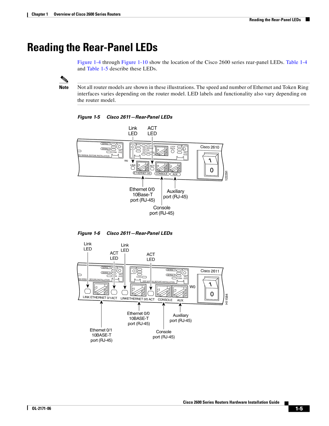
Reading the Rear-Panel LEDs
Cisco 2613-Rear-Panel LEDs
ACT
Link
FDX
CF1
Modules, Interface Cards, and Memory
WAN and LAN Interface Numbering
Interface Numbering
11 Interface Numbering in Chassis with 1-RU Height
Description Specification
System Specifications
Voice Interface Numbering
Regulatory Compliance
Safety with Electricity
Safety Recommendations
Preventing Electrostatic Discharge Damage
Power Source Input Power Tolerance Limits
Power Supply Considerations
General Site Requirements
Site Environment
Site Configuration
Installation Checklist
Equipment Racks
Task Verified by Date
Creating a Site Log
Inspecting the Router
Tools and Equipment for Installation and Maintenance
Console Port Connections
Console and Auxiliary Port Considerations
Auxiliary Port Connections
Preparing to Connect to a Network
Token Ring Connections
Ethernet Connections
Serial Connections
Configuring Serial Connections
Serial DTE or DCE Devices
Distance Limitations
Signaling Standards Supported
Device Type Gender Typical Devices
Asynchronous/Synchronous Serial Module Baud Rates
Isdn BRI Connections
EIA/TIA-232
Distance EIA-530 Distance Rate bps Feet Meters
Low-Capacitance Cable
56-K/Switched-56-kbps DSU/CSU Connections
OL-2171-06
Installing the Router
For network modules
Installing Modules, Interface Cards, and Power Supplies
For WICs and VICs
For AIMs
Setting the Chassis on a Desktop
Setting Up the Chassis
For internal power supplies
For external power supplies
Mounting the Chassis in a Rack
Right
To the other side of the chassis. Brackets for 19-inch rack
Brackets for 19-inch rack
To the other side of the chassis
Use two screws on each side For 19-inch rack Right bracket
Attaching the Brackets to a Router of 2-RU Height
V0 EN
Installing the Router in a Rack
Attaching Rubber Feet to the Router
Mounting the Chassis on the Wall
Attaching Wall-Mount Brackets to the Router
16 Attaching the Wall-Mount Brackets
Mounting the Router on the Wall
17 Mounting the Chassis on the Wall
Installing the Chassis Ground Connection
Ring terminal
Connecting Routers to AC Power
Power Connections
DC Wiring Requirements
Connecting Routers to a DC-Input Power Supply
Router DC Input DC Input Wire Size1
15A, 120VAC 10A, 240VAC. Statement
Wiring Procedure for DC Input
Connecting Routers to the Cisco Redundant Power System
Connecting WAN, LAN, and Voice Cables
Ports and Cabling
Port or Connection Port Type, Color Connected To Cable
LAN, WAN, and Voice Connection Procedures
Connecting to the Console Port
Connecting to a Console Terminal or Modem
23 Connecting to a Console Terminal
Connecting to the Auxiliary Port
Identifying a Rollover Cable
24 Connecting a Modem to the Auxiliary Port
Checklist for Power Up
Powering Up the Router
Front Panel Indicators
Routers with 1-RU Chassis Height
Routers with 2-RU Chassis Height
Power-Up Procedure
Configuring the Router
Initial Configuration Using the Setup Command Facility
Initial Configuration Using SDM
Enter a hostname for the router this example uses
Configuration is displayed
Initial Configuration Using the CLI Manual Configuration
To proceed with manual configuration using the CLI, enter no
OL-2171-06
Isolating Problems
Troubleshooting
Environmental Reporting Features
Troubleshooting the Power and Cooling Systems
Troubleshooting Modules, Cables, and Connections
System Messages
Recovering a Lost Password
Cisco Technical Assistance Center
Entering ROM Monitor Mode
Using the ROM Monitor
Enter ROM Monitor Mode by Using the reload Command
ROM Monitor Commands
Command abc
ROM Monitor Command Syntax Conventions
Router Management Commands
ROM Monitor Command Descriptions
Boot Commands in the ROM Monitor
Informational Commands in the ROM Monitor
Other Useful ROM Monitor Commands
Debugging Commands
Modifying the Configuration Register in Menu Mode
Configuration Register Commands
Modifying the Configuration Register by Hexidecimal Entry
Recovering Cisco IOS Software Images
Description and Options of the xmodem Command
Copying an Image from the Console Using the xmodem Command
Procedure for the xmodem Command
Console Requirements
Restrictions on the tftpdnld Command
Specify the required variables, for example
Procedure for the tftpdnld Command
DEFAULTGATEWAY=172.16.19.1
Bit Number Hexadecimal Meaning
Configuration Register Settings
Nvram
Changing Configuration Register Settings
Boot Field Meaning
Configuring the Boot Field
Bit Address net host
Baud Bit
Enabling Booting from Flash Memory
OL-2171-06
IN-1
Numerics
IN-2
Dram
LAN
Isdn BRI
Link LED
IN-3
IN-4
Sdram
IN-5
IN-6