Chapter 3 Installing the Router
Connecting WAN, LAN, and Voice Cables
Connecting Routers to the Cisco Redundant Power System
If your router uses the Cisco Redundant Power System (RPS), refer to the Cisco RPS Hardware Installation Guide for instructions about the power connections. You can access this document at the location described in the“Obtaining Documentation” section on page xvii.
Connecting WAN, LAN, and Voice Cables
This chapter describes how to connect the WAN, LAN, and voice interface cables. It includes the following sections:
•“Ports and Cabling” section on page
•“LAN, WAN, and Voice Connection Procedures” section on page
Note One or two Ethernet cables are typically provided with the router. Additional cables and transceivers can be ordered from Cisco. For ordering information, refer to the Cisco Product Catalog at http://www.cisco.com/en/US/products/products_catalog_links_launch.html. For cable pinouts, refer to the Cisco Modular Access Router Cable Specifications document available online and on the Documentation
Warning Do not work on the system, or connect or disconnect cables during periods of lightning activity.
Statement 1001
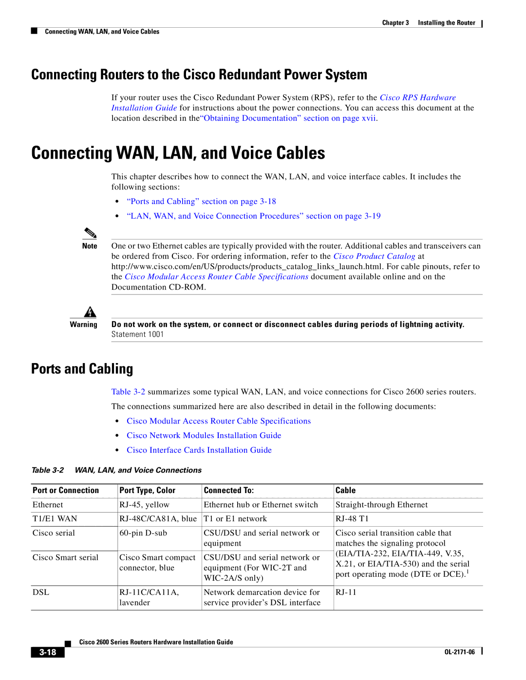
Ports and Cabling
Table
•Cisco Modular Access Router Cable Specifications
•Cisco Network Modules Installation Guide
•Cisco Interface Cards Installation Guide
Table
| Port or Connection | Port Type, Color | Connected To: | Cable | |||
|
|
|
|
| |||
| Ethernet | Ethernet hub or Ethernet switch | |||||
|
|
|
|
| |||
| T1/E1 WAN | T1 or E1 network | |||||
|
|
|
|
| |||
| Cisco serial | CSU/DSU and serial network or | Cisco serial transition cable that | ||||
|
|
|
|
| equipment | matches the signaling protocol | |
|
|
|
|
|
| ||
| Cisco Smart serial | Cisco Smart compact | CSU/DSU and serial network or | ||||
| X.21, or | ||||||
|
|
|
| connector, blue | equipment (For | ||
|
|
|
| port operating mode (DTE or DCE).1 | |||
|
|
|
|
| |||
|
|
|
|
|
|
| |
|
|
|
|
| |||
| DSL | Network demarcation device for | |||||
|
|
|
| lavender | service provider’s DSL interface |
|
|
|
|
|
|
|
|
|
|
|
|
| Cisco 2600 Series Routers Hardware Installation Guide |
|
| ||
|
|
|
|
| |||
|
|
|
|
|
|
|
|
|
|
|
|
|
|
| |
|
|
|
|
|
| ||