Audience
Installing WAN and Voice Interface Cards, page
Configuring Voice-over-IP, page List of Terms, page
Audience, page Conventions, page
Installing WAN and Voice Interface Cards
If You Are Installing Voice Interface Cards
Conventions
WIC and VIC Installation Procedure
Connecting the FXS, FXO, and E&M VICs to the Network
Figure 2 Inserting a WIC or VIC in the Router
Connector Pinouts for FXS, FXO, and E&M VICs
Signal
Description
Checking FXS VIC Installation
2-Port ISDN BRI Card
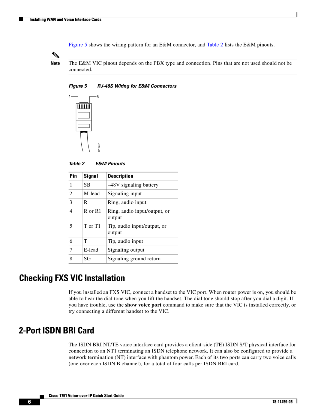
RJ-48S Wiring for E&M Connectors
Connecting the 2-Port ISDN BRI Card
NT Interface use
Determining Voice Port Numbering
ISDN BRI Card LEDs
TE Interface use
Cisco Router and Security Device Manager
Example
Configuring Voice-over-IP
Configuration Tools
Cisco ConfigMaker Application
Major Voice over IP Configuration Tasks
Cisco IOS Command-Line Interface
Entering Configuration Mode
Information for International Users
Saving the Configuration
Router# show startup-config
Dial Plan
Wildcards and Number Expansion
Westconfig-dial-peer# port 0/0
Destination
Configuring FXS Interfaces
Num-Exp Command Entry
Extension
Voice Port
Local Dial Peers
Telephone Number
Dial-Peer Tag
These commands are summarized in Figure
Figure 13 Basic Voice Network East Router
Destination Pattern
Figure 14 East Router Configured for Local Dial Peers
919 FXS VIC 1/0
Remote Location
Checking Dial Peer Configuration
Calling Between Routers
Destination Pattern
1919555
Other Routers on the Network
Configuring FXO Interfaces
Checking FXS Configuration
Remote Location
Figure 18 FXO Gateway to PSTN
West
Command
Configuring E&M Interfaces
Checking FXO Configuration
signal wink-start immediate delay-dial
Figure 20 Linking PBXs over the IP Network Remote Dial Peers
Tuning Parameters for Real-Time Voice Traffic
Checking E&M Interface Configuration
Need for Quality of Service
IP Precedence
Configuring RSVP
RSVP
Multilink PPP Interleaving
Routerconfig-if# ip rtp reserve lowest-UDP-port range-of-ports
Configuring Multilink PPP Interleaving
Configuring RTP Header Compression
RTP Header Compression
Configuring Frame Relay for VoIP
List of Terms
Obtaining Documentation
Cisco.com
Ordering Documentation
Obtaining Technical Assistance
Submitting a Service Request
Documentation Feedback
Cisco Technical Support Website
Definitions of Service Request Severity
Obtaining Additional Publications and Information
iQ Magazine is the quarterly publication from Cisco Systems designed to help growing companies learn how they can use technology to increase revenue, streamline their business, and expand services. The publication identifies the challenges facing these companies and the technologies to help solve them, using real-world case studies and business strategies to help readers make sound technology investment decisions. You can access iQ Magazine at this URL