Connecting Cisco ISDN PRI Network Modules to the Network
PRI Module LEDs
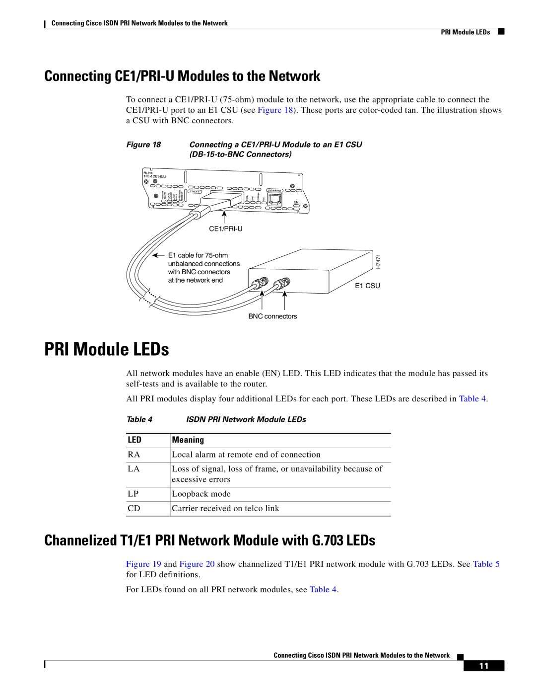
Connecting CE1/PRI-U Modules to the Network
To connect a
Figure 18 Connecting a CE1/PRI-U Module to an E1 CSU (DB-15-to-BNC Connectors)
|
|
|
|
|
|
| |
REMOTE ALARM | LOCAL ALARM | LOOP BACK | CARRIER DETECT |
CTRLR 0
|
|
|
| 10/100BaseT |
COLL | LINK | 100Mbps | FDX | EN |
|
|
|
|
E1 cable for
H7471
E1 CSU
BNC connectors
PRI Module LEDs
All network modules have an enable (EN) LED. This LED indicates that the module has passed its
All PRI modules display four additional LEDs for each port. These LEDs are described in Table 4.
Table 4 | ISDN PRI Network Module LEDs |
|
|
LED | Meaning |
|
|
RA | Local alarm at remote end of connection |
|
|
LA | Loss of signal, loss of frame, or unavailability because of |
| excessive errors |
|
|
LP | Loopback mode |
|
|
CD | Carrier received on telco link |
|
|
Channelized T1/E1 PRI Network Module with G.703 LEDs
Figure 19 and Figure 20 show channelized T1/E1 PRI network module with G.703 LEDs. See Table 5 for LED definitions.
For LEDs found on all PRI network modules, see Table 4.
Connecting Cisco ISDN PRI Network Modules to the Network
11