Connecting Cisco ISDN PRI Network Modules to the Network
PRI Module LEDs
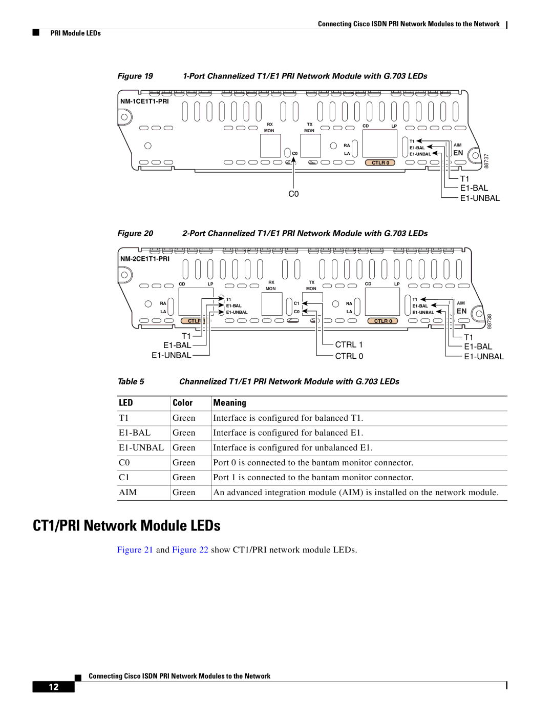
Figure 19 1-Port Channelized T1/E1 PRI Network Module with G.703 LEDs
RX | TX | CD | LP |
MON | MON |
|
|
|
| RA | T1 |
|
| ||
|
|
| |
C0 |
| LA |
CTLR 0
C0
AIM
EN | 88737 |
|
T1
Figure 20 2-Port Channelized T1/E1 PRI Network Module with G.703 LEDs
CD | LP | RX | TX |
CDLP
RA
MON | MON | |
T1 | C1 | |
|
RA
T1
AIM
LA
CTLR 1
T1
C0 |
LA |
CTLR 0
CTRL 1
CTRL 0
EN
88738
T1
Table 5 | Channelized T1/E1 PRI Network Module with G.703 LEDs |
LED | Color | Meaning |
|
|
|
T1 | Green | Interface is configured for balanced T1. |
|
|
|
Green | Interface is configured for balanced E1. | |
|
|
|
| Green | Interface is configured for unbalanced E1. |
|
|
|
C0 | Green | Port 0 is connected to the bantam monitor connector. |
|
|
|
C1 | Green | Port 1 is connected to the bantam monitor connector. |
|
|
|
AIM | Green | An advanced integration module (AIM) is installed on the network module. |
|
|
|
CT1/PRI Network Module LEDs
Figure 21 and Figure 22 show CT1/PRI network module LEDs.
Connecting Cisco ISDN PRI Network Modules to the Network
12
