Connecting Cisco ISDN PRI Network Modules to the Network
Channelized T1/E1 PRI Network Modules with G.703
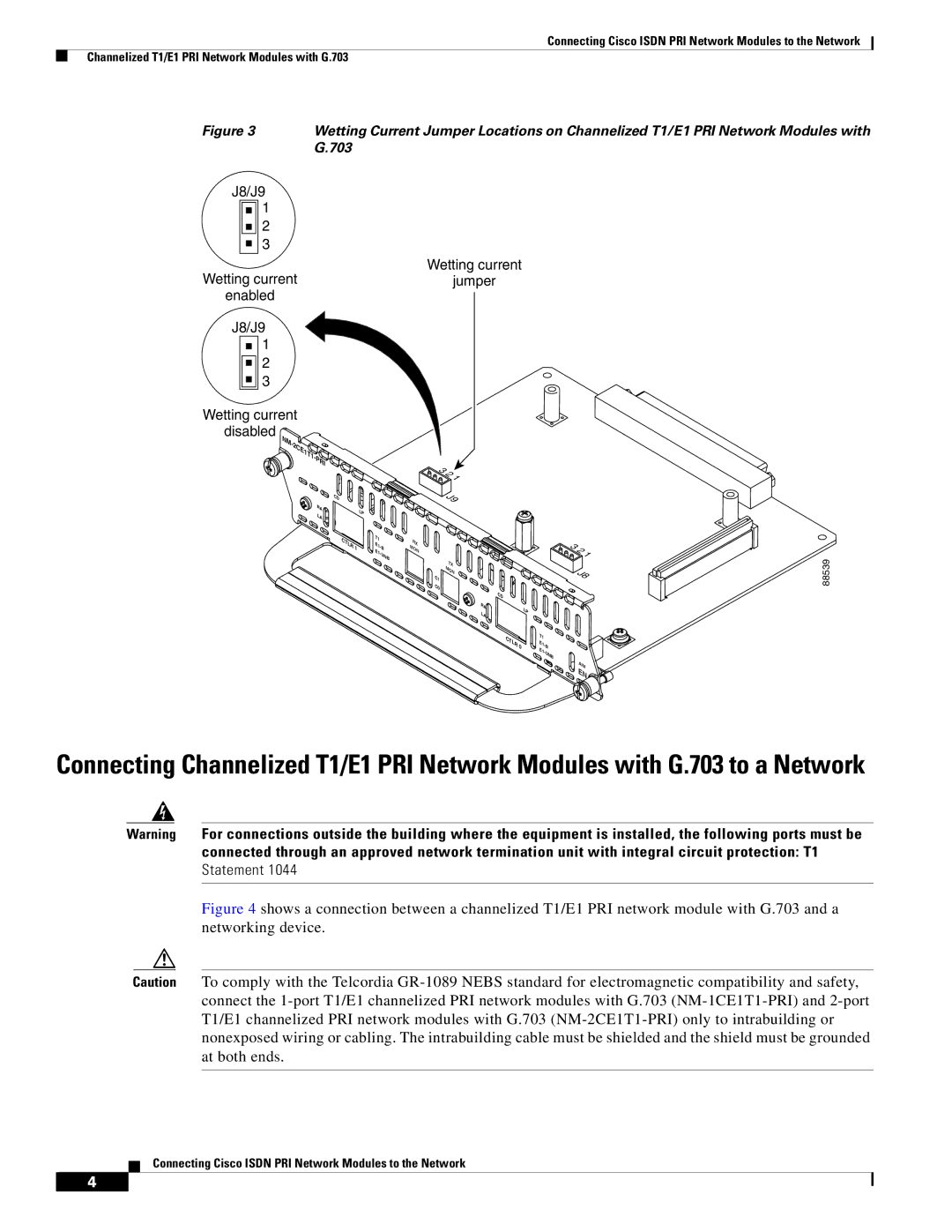
Figure 3 | Wetting Current Jumper Locations on Channelized T1/E1 PRI Network Modules with |
| G.703 |
J8/J9
1
2
3
Wetting current
Wetting currentjumper enabled
J8/J9
1
2
3
Wetting current
disabled NM-
| CD | |
RA | LP | |
LA | ||
| ||
| CTLR | |
| 1 |
![]() 1
1
J9
T1 | RX |
E1- | |
E1- | MON |
B |
|
UNB |
|
TX
MON
C1
C0
![]() 1
1
J8
| CD | |
RA | LP | |
LA | ||
|
88539
CTLR 0
T1
AIM EN
Connecting Channelized T1/E1 PRI Network Modules with G.703 to a Network
Warning For connections outside the building where the equipment is installed, the following ports must be connected through an approved network termination unit with integral circuit protection: T1 Statement 1044
Figure 4 shows a connection between a channelized T1/E1 PRI network module with G.703 and a networking device.
Caution To comply with the Telcordia
Connecting Cisco ISDN PRI Network Modules to the Network
4
