Installing and Removing the Supervisor Engine
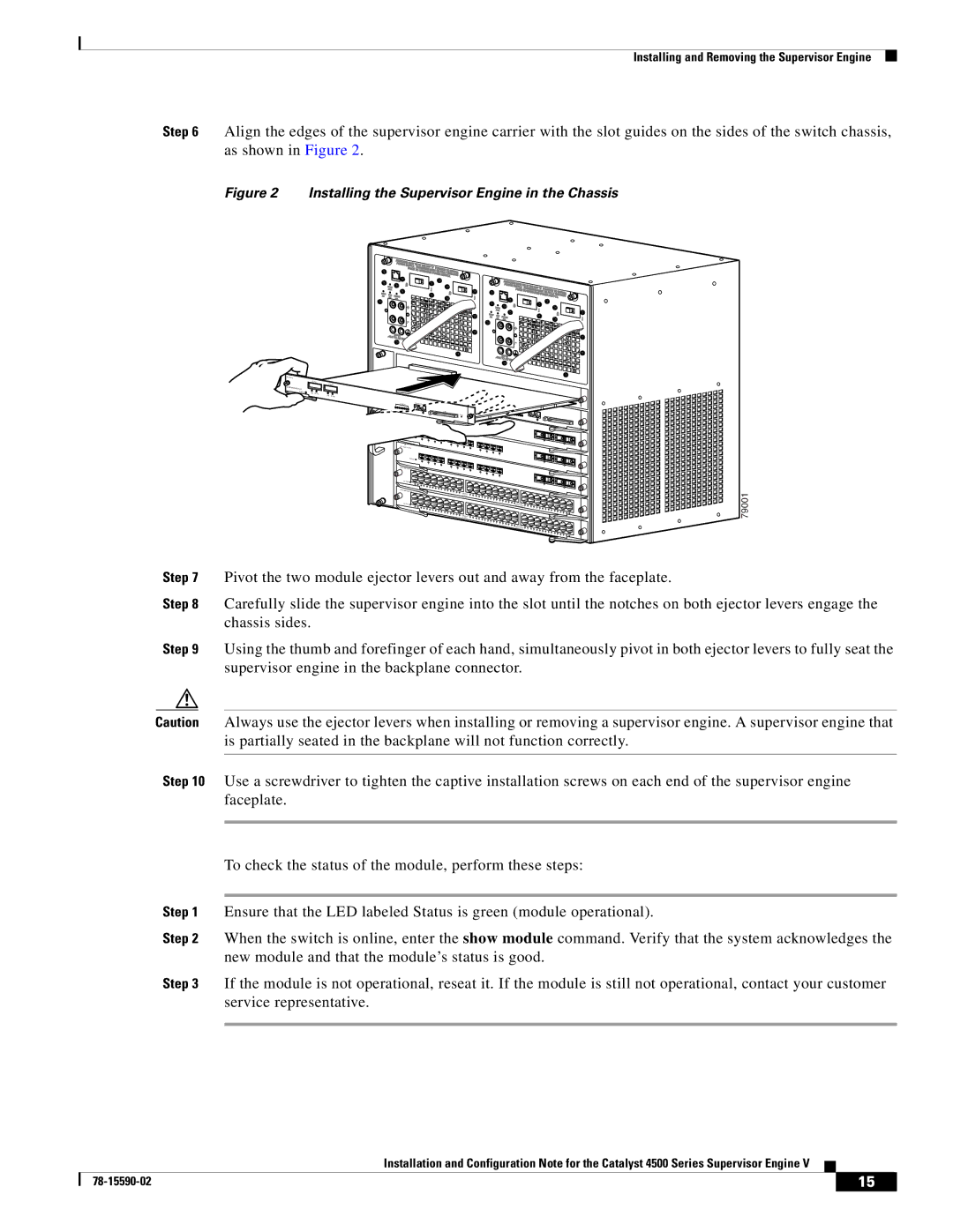
Step 6 Align the edges of the supervisor engine carrier with the slot guides on the sides of the switch chassis, as shown in Figure 2.
Figure 2 Installing the Supervisor Engine in the Chassis
SUPERVISOR III ENGINE STATUS ![]()
UPLINK 1
UPLINK 2
LINK ACTIVE
LINK ACTIVE
-
STATUS ![]()
1
2 |
|
3 | 4 |
WS- |
| 5 |
| |
|
| 6 | 7 | |
| STATUS |
|
|
|
| 1 | 2 |
|
|
|
| 3 | 4 |
|
| 5 |
| ||
| 6 | 7 | ||
| STATUS |
|
|
|
| 1 | 2 |
|
|
|
| 3 | 4 |
|
|
|
| 5 |
|
|
|
| 6 | 7 |
CONSOLE 10/100
8 |
|
|
9 | 10 |
|
| 11 | 12 |
|
| 17 |
8 |
|
|
9 | 10 |
|
| 11 | 12 |
17 |
8 |
|
|
9 | 10 |
|
| 11 | 12 |
17 |
| 79001 |
Step 7 | Pivot the two module ejector levers out and away from the faceplate. |
Step 8 | Carefully slide the supervisor engine into the slot until the notches on both ejector levers engage the |
| chassis sides. |
Step 9 Using the thumb and forefinger of each hand, simultaneously pivot in both ejector levers to fully seat the supervisor engine in the backplane connector.
Caution Always use the ejector levers when installing or removing a supervisor engine. A supervisor engine that is partially seated in the backplane will not function correctly.
Step 10 Use a screwdriver to tighten the captive installation screws on each end of the supervisor engine faceplate.
To check the status of the module, perform these steps:
Step 1 Ensure that the LED labeled Status is green (module operational).
Step 2 When the switch is online, enter the show module command. Verify that the system acknowledges the new module and that the module’s status is good.
Step 3 If the module is not operational, reseat it. If the module is still not operational, contact your customer service representative.
Installation and Configuration Note for the Catalyst 4500 Series Supervisor Engine V
| 15 |
| |
|
|
