Attaching Module Interface Cables
Warning Blank faceplates and cover panels serve three important functions: they prevent exposure to hazardous voltages and currents inside the chassis; they contain electromagnetic interference (EMI) that might disrupt other equipment; and they direct the flow of cooling air through the chassis. Do not operate the system unless all cards, faceplates, front covers, and rear covers are in place. Statement 1029
Step 7 If the slot is to remain empty, install a
Attaching Module Interface Cables
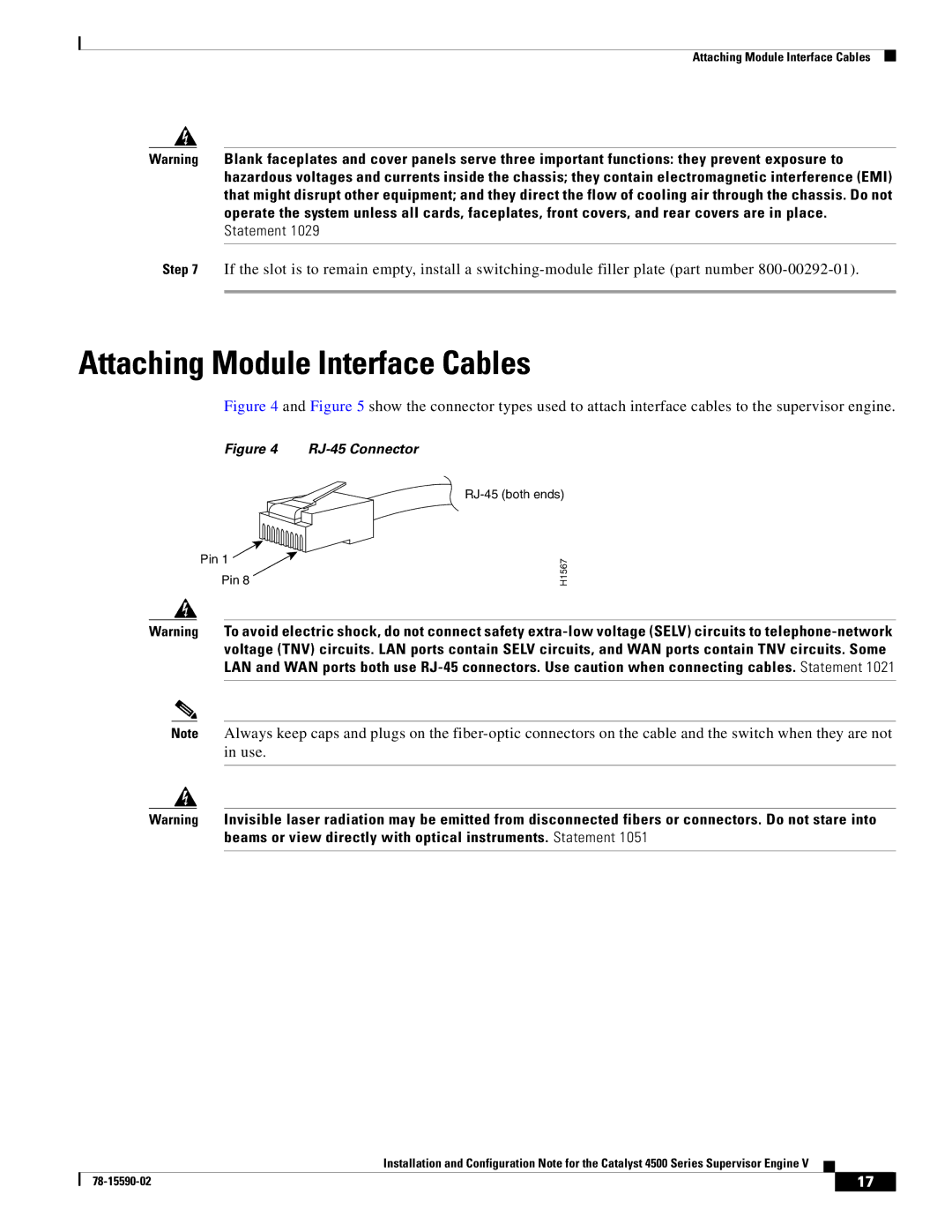
Figure 4 and Figure 5 show the connector types used to attach interface cables to the supervisor engine.
Figure 4 RJ-45 Connector
Pin 1
Pin 8
H1567
Warning To avoid electric shock, do not connect safety
Note Always keep caps and plugs on the
Warning Invisible laser radiation may be emitted from disconnected fibers or connectors. Do not stare into beams or view directly with optical instruments. Statement 1051
Installation and Configuration Note for the Catalyst 4500 Series Supervisor Engine V
| 17 |
| |
|
|