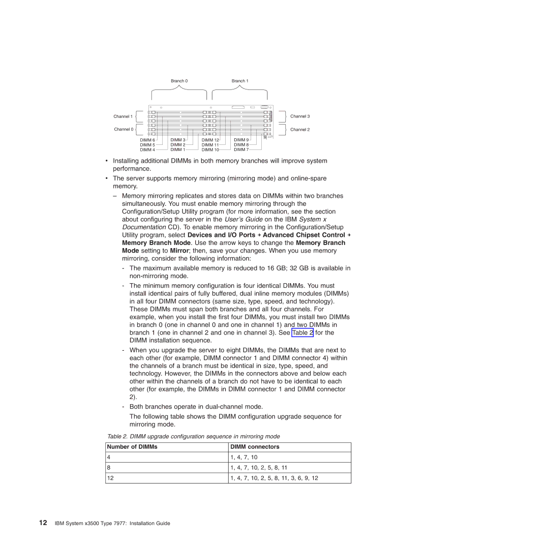
Branch 0 | Branch 1 |
Channel 1
Channel 0
DIMM 6 | DIMM 3 | DIMM 12 | DIMM 9 |
DIMM 5 | DIMM 2 | DIMM 11 | DIMM 8 |
DIMM 4 | DIMM 1 | DIMM 10 | DIMM 7 |
Channel 3
Channel 2
vInstalling additional DIMMs in both memory branches will improve system performance.
vThe server supports memory mirroring (mirroring mode) and
–Memory mirroring replicates and stores data on DIMMs within two branches simultaneously. You must enable memory mirroring through the Configuration/Setup Utility program (for more information, see the section about configuring the server in the User’s Guide on the IBM System x Documentation CD). To enable memory mirroring in the Configuration/Setup Utility program, select Devices and I/O Ports → Advanced Chipset Control → Memory Branch Mode. Use the arrow keys to change the Memory Branch Mode setting to Mirror; then, save your changes. When you use memory mirroring, consider the following information:
-The maximum available memory is reduced to 16 GB; 32 GB is available in
-The minimum memory configuration is four identical DIMMs. You must install identical pairs of fully buffered, dual inline memory modules (DIMMs) in all four DIMM connectors (same size, type, speed, and technology). These DIMMs must span both branches and all four channels. For example, when you install the first four DIMMs, you must install two DIMMs in branch 0 (one in channel 0 and one in channel 1) and two DIMMs in branch 1 (one in channel 2 and one in channel 3). See Table 2 for the DIMM installation sequence.
-When you upgrade the server to eight DIMMs, the DIMMs that are next to each other (for example, DIMM connector 1 and DIMM connector 4) within the channels of a branch must be identical in size, type, speed, and technology. However, the DIMMs in the connectors above and below each other within the channels of a branch do not have to be identical to each other (for example, the DIMMs in DIMM connector 1 and DIMM connector 2).
-Both branches operate in
The following table shows the DIMM configuration upgrade sequence for mirroring mode.
Table 2. DIMM upgrade configuration sequence in mirroring mode
Number of DIMMs | DIMM connectors |
|
|
4 | 1, 4, 7, 10 |
|
|
8 | 1, 4, 7, 10, 2, 5, 8, 11 |
|
|
12 | 1, 4, 7, 10, 2, 5, 8, 11, 3, 6, 9, 12 |
|
|