GBIC Handling Guidelines and Installation
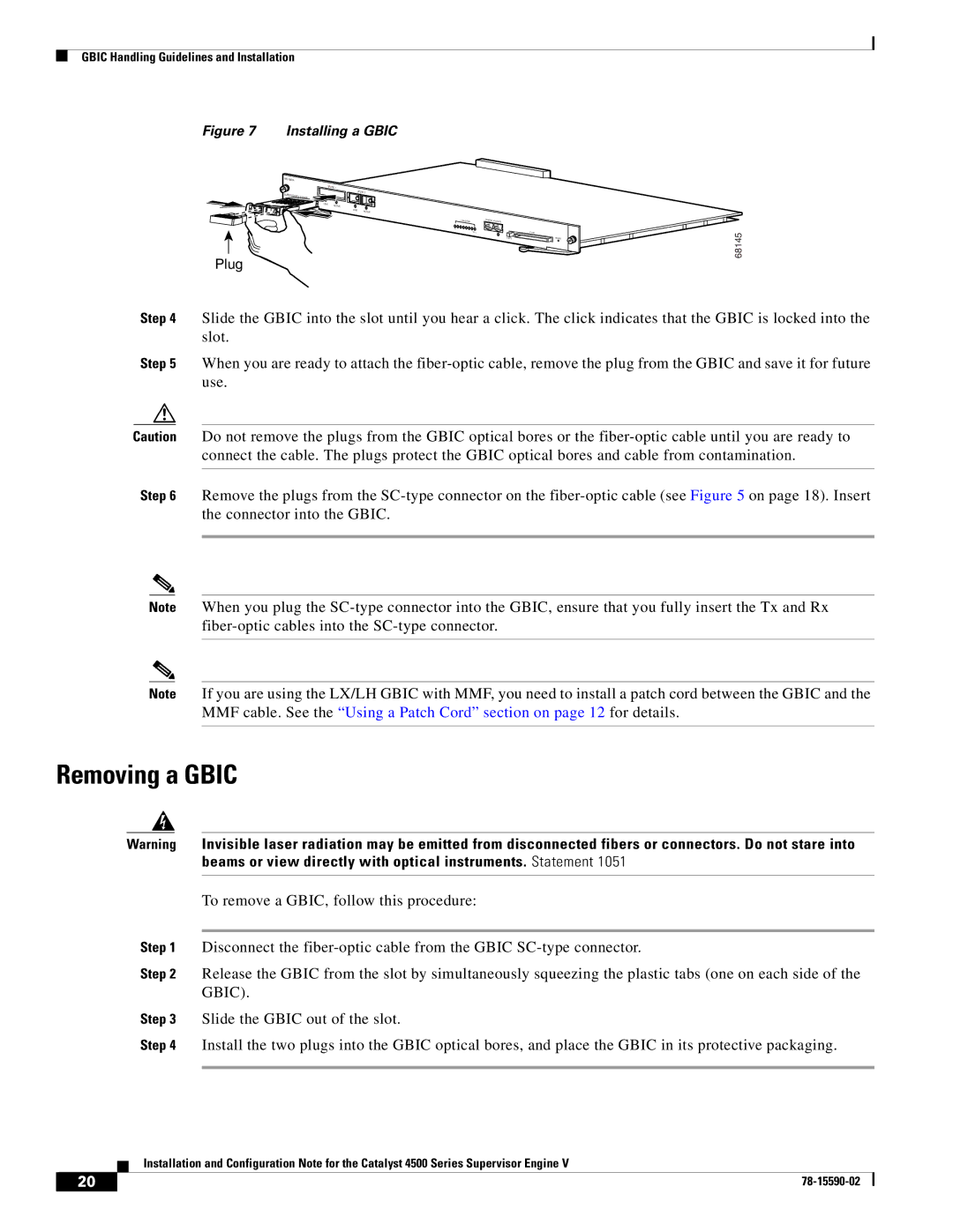
Figure 7 Installing a GBIC
| |
| UPLINK 1 |
SUPERVISOR III ENGINE | UPLINK 2 |
| |
LINK | ACTIVE |
|
LINK | ACTIVE |
UTILIZATION | CONSOLE 10/100 MGT |
|
1% |
|
|
| 100% | FLASH |
| EJECT | RESET |
Plug
68145
Step 4 Slide the GBIC into the slot until you hear a click. The click indicates that the GBIC is locked into the slot.
Step 5 When you are ready to attach the
Caution Do not remove the plugs from the GBIC optical bores or the
Step 6 Remove the plugs from the
Note When you plug the
Note If you are using the LX/LH GBIC with MMF, you need to install a patch cord between the GBIC and the MMF cable. See the “Using a Patch Cord” section on page 12 for details.
Removing a GBIC
Warning Invisible laser radiation may be emitted from disconnected fibers or connectors. Do not stare into beams or view directly with optical instruments. Statement 1051
To remove a GBIC, follow this procedure:
Step 1 Disconnect the
Step 2 Release the GBIC from the slot by simultaneously squeezing the plastic tabs (one on each side of the GBIC).
Step 3 Slide the GBIC out of the slot.
Step 4 Install the two plugs into the GBIC optical bores, and place the GBIC in its protective packaging.
Installation and Configuration Note for the Catalyst 4500 Series Supervisor Engine V
20 |
| |
|