CBM-710/720 Service Manual
9.RS422A Interface Circuit
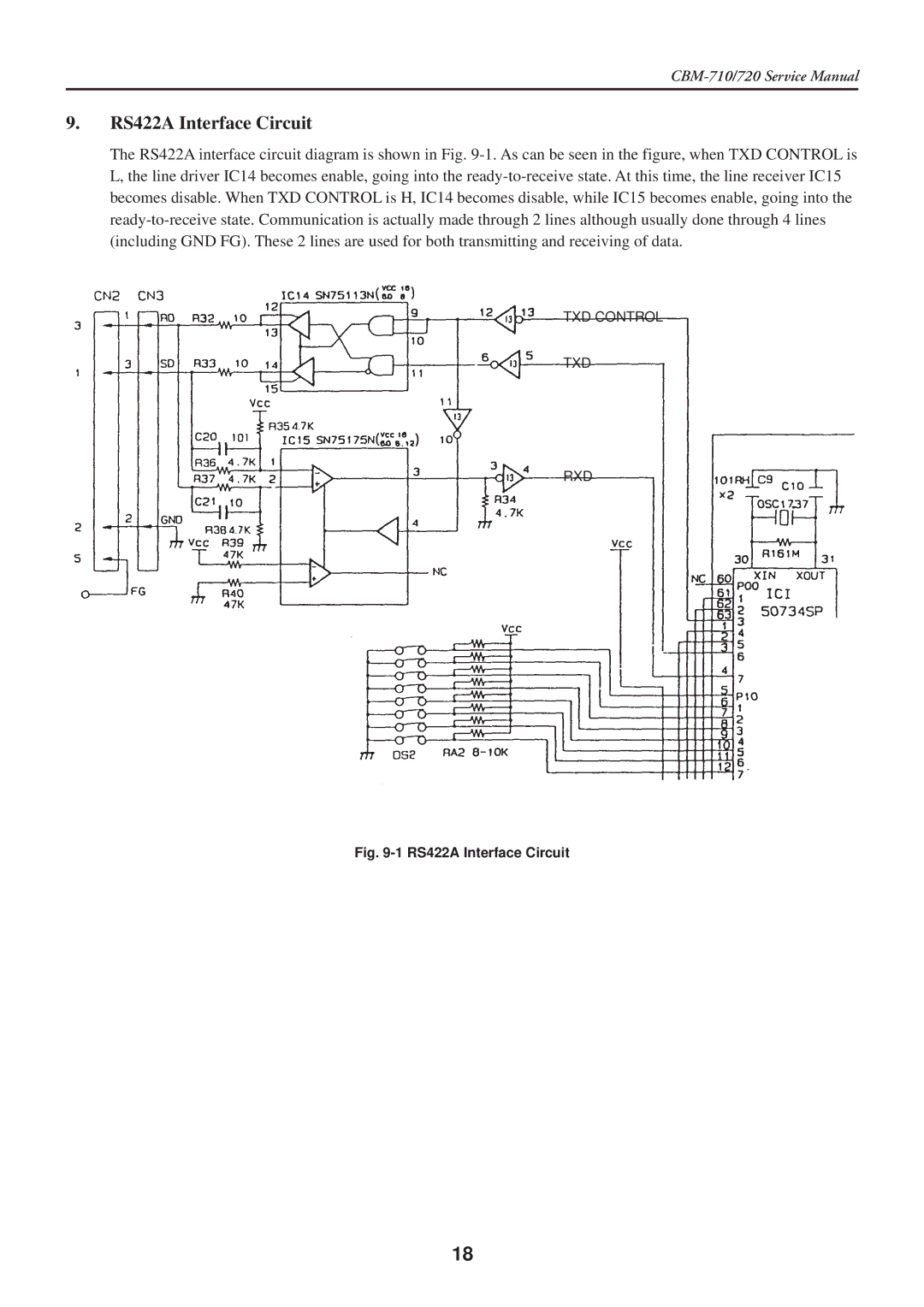
The RS422A interface circuit diagram is shown in Fig. 9-1. As can be seen in the figure, when TXD CONTROL is L, the line driver IC14 becomes enable, going into the ready-to-receive state. At this time, the line receiver IC15 becomes disable. When TXD CONTROL is H, IC14 becomes disable, while IC15 becomes enable, going into the ready-to-receive state. Communication is actually made through 2 lines although usually done through 4 lines (including GND FG). These 2 lines are used for both transmitting and receiving of data.
TXD CONTROL
TXD
RXD
Fig. 9-1 RS422A Interface Circuit