5.Interface with Operation Panel
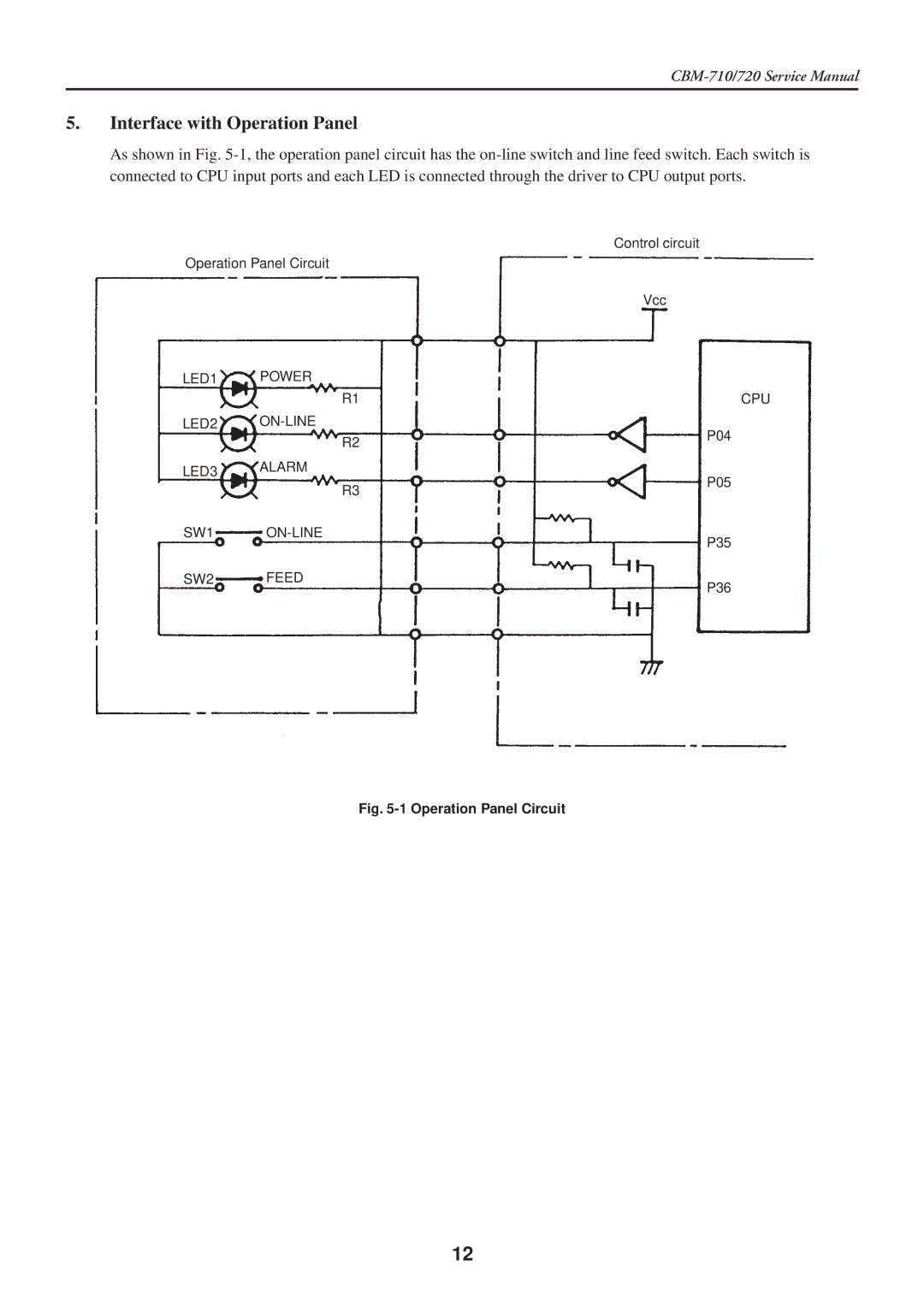
As shown in Fig.
Control circuit
Operation Panel Circuit
Vcc
LED1 | POWER |
|
| R1 | CPU |
LED2 | P04 | |
| R2 | |
|
| |
LED3 | ALARM | P05 |
| ||
| R3 | |
|
| |
SW1 | P35 | |
|
| |
SW2 | FEED | P36 |
|
|
Fig. 5-1 Operation Panel Circuit
12
As shown in Fig.
Control circuit
Operation Panel Circuit
Vcc
LED1 | POWER |
|
| R1 | CPU |
LED2 | P04 | |
| R2 | |
|
| |
LED3 | ALARM | P05 |
| ||
| R3 | |
|
| |
SW1 | P35 | |
|
| |
SW2 | FEED | P36 |
|
|
12