10.Power Circuit
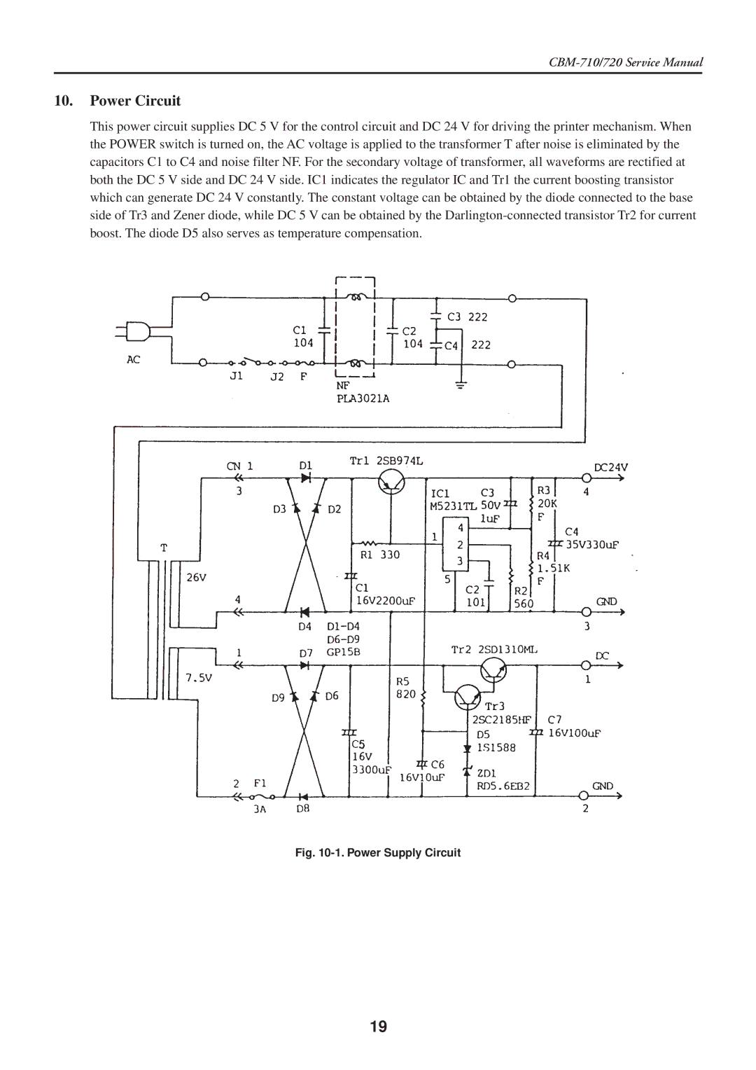
This power circuit supplies DC 5 V for the control circuit and DC 24 V for driving the printer mechanism. When the POWER switch is turned on, the AC voltage is applied to the transformer T after noise is eliminated by the capacitors C1 to C4 and noise filter NF. For the secondary voltage of transformer, all waveforms are rectified at both the DC 5 V side and DC 24 V side. IC1 indicates the regulator IC and Tr1 the current boosting transistor which can generate DC 24 V constantly. The constant voltage can be obtained by the diode connected to the base side of Tr3 and Zener diode, while DC 5 V can be obtained by the
Fig. 10-1. Power Supply Circuit
19