APX280M APX490M manual.qxd 2/6/2008 11:38 AM Page 4
English
APX290M/APX490M Power System Amplifier
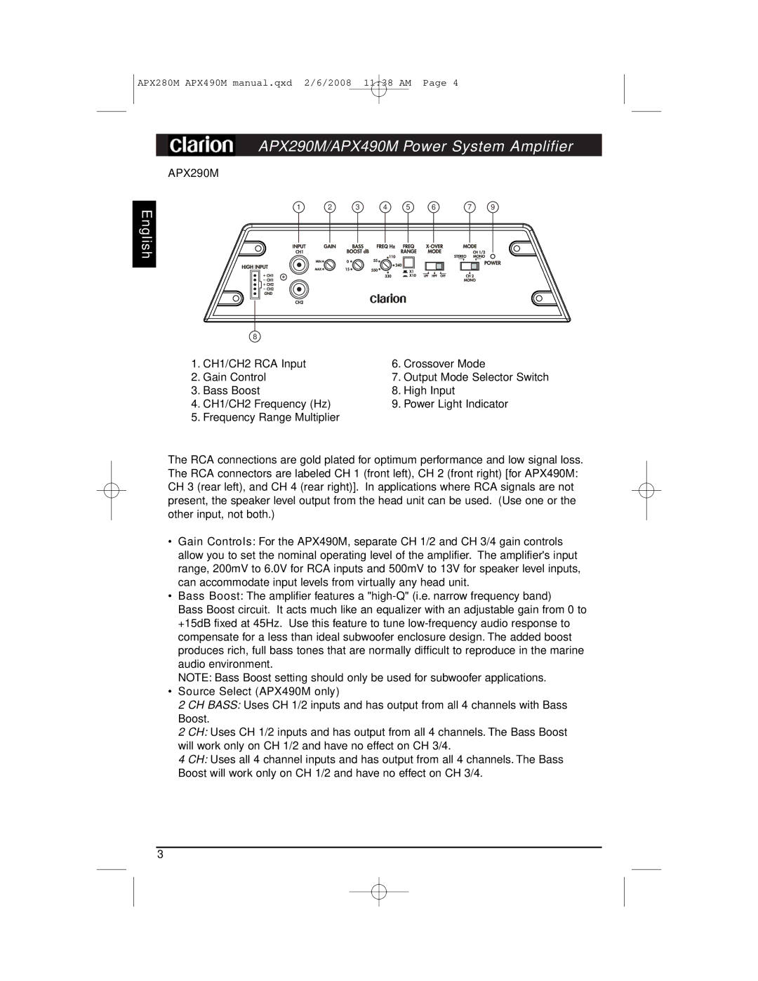
APX290M
1 | 2 | 3 | 4 | 5 | 6 | 7 | 9 |
| 8 |
|
|
1. CH1/CH2 RCA Input | 6. Crossover Mode | ||
2. | Gain Control | 7. | Output Mode Selector Switch |
3. | Bass Boost | 8. | High Input |
4. CH1/CH2 Frequency (Hz) | 9. Power Light Indicator | ||
5. | Frequency Range Multiplier |
|
|
The RCA connections are gold plated for optimum performance and low signal loss. The RCA connectors are labeled CH 1 (front left), CH 2 (front right) [for APX490M: CH 3 (rear left), and CH 4 (rear right)]. In applications where RCA signals are not present, the speaker level output from the head unit can be used. (Use one or the other input, not both.)
•Gain Controls: For the APX490M, separate CH 1/2 and CH 3/4 gain controls allow you to set the nominal operating level of the amplifier. The amplifier's input range, 200mV to 6.0V for RCA inputs and 500mV to 13V for speaker level inputs, can accommodate input levels from virtually any head unit.
•Bass Boost: The amplifier features a
Bass Boost circuit. It acts much like an equalizer with an adjustable gain from 0 to +15dB fixed at 45Hz. Use this feature to tune
NOTE: Bass Boost setting should only be used for subwoofer applications.
•Source Select (APX490M only)
2 CH BASS: Uses CH 1/2 inputs and has output from all 4 channels with Bass Boost.
2 CH: Uses CH 1/2 inputs and has output from all 4 channels. The Bass Boost will work only on CH 1/2 and have no effect on CH 3/4.
4 CH: Uses all 4 channel inputs and has output from all 4 channels. The Bass Boost will work only on CH 1/2 and have no effect on CH 3/4.
3