APX280M APX490M manual.qxd 2/6/2008 11:38 AM Page 3
Operation/Installation Manual
DESCRIPTION
The APX290M and APX490M use an unregulated MOSFET power supply for superior sound and output wattage. In addition, a
All of the connections and controls for the APX290M and APX490M are conve- niently located at the ends of the amplifier and labeled appropriately. To ensure the best possible electrical connections, the power, speaker, and RCA inputs are
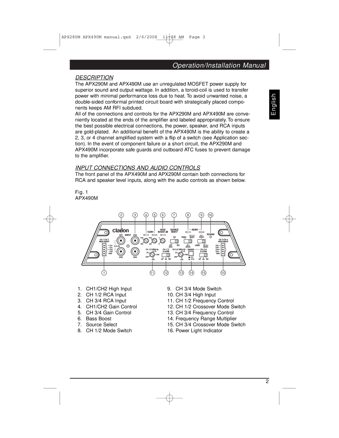
INPUT CONNECTIONS AND AUDIO CONTROLS
The front panel of the APX490M and APX290M contain both connections for RCA and speaker level inputs, along with the audio controls as shown below.
Fig. 1
APX490M
English
2 | 3 | 4 | 5 | 6 | 7 | 8 | 9 | 16 |
111 12 13 14 15 10
1. | CH1/CH2 High Input | 9. | CH 3/4 Mode Switch |
2. | CH 1/2 RCA Input | 10. | CH 3/4 High Input |
3. | CH 3/4 RCA Input | 11. | CH 1/2 Frequency Control |
4. | CH1/CH2 Gain Control | 12. | CH 1/2 Crossover Mode Switch |
5. | CH 3/4 Gain Control | 13. | CH 3/4 Frequency Control |
6. | Bass Boost | 14. | Frequency Range Multiplier |
7. | Source Select | 15. | CH 3/4 Crossover Mode Switch |
8. | CH 1/2 Mode Switch | 16. | Power Light Indicator |
2