S E T U P
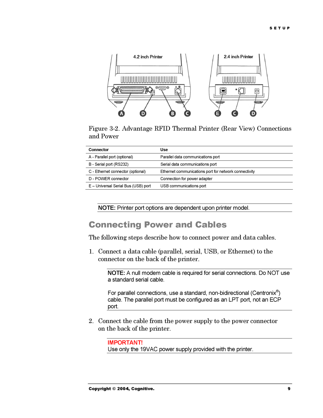
Figure 3-2. Advantage RFID Thermal Printer (Rear View) Connections and Power
Connector | Use |
A - Parallel port (optional) | Parallel data communications port |
|
|
B - Serial port (RS232) | Serial data communications port |
|
|
C - Ethernet connector (optional) | Ethernet communications port for network connectivity |
|
|
D - POWER connector | Connection for power adapter |
|
|
E – Universal Serial Bus (USB) port | USB communications port |
NOTE: Printer port options are dependent upon printer model.
Connecting Power and Cables
The following steps describe how to connect power and data cables.
1.Connect a data cable (parallel, serial, USB, or Ethernet) to the connector on the back of the printer.
NOTE: A null modem cable is required for serial connections. Do NOT use a standard serial cable.
For parallel connections, use a standard,
2.Connect the cable from the power supply to the power connector on the back of the printer.
IMPORTANT!
Use only the 19VAC power supply provided with the printer.
Copyright © 2004, Cognitive. | 9 |