Step
3
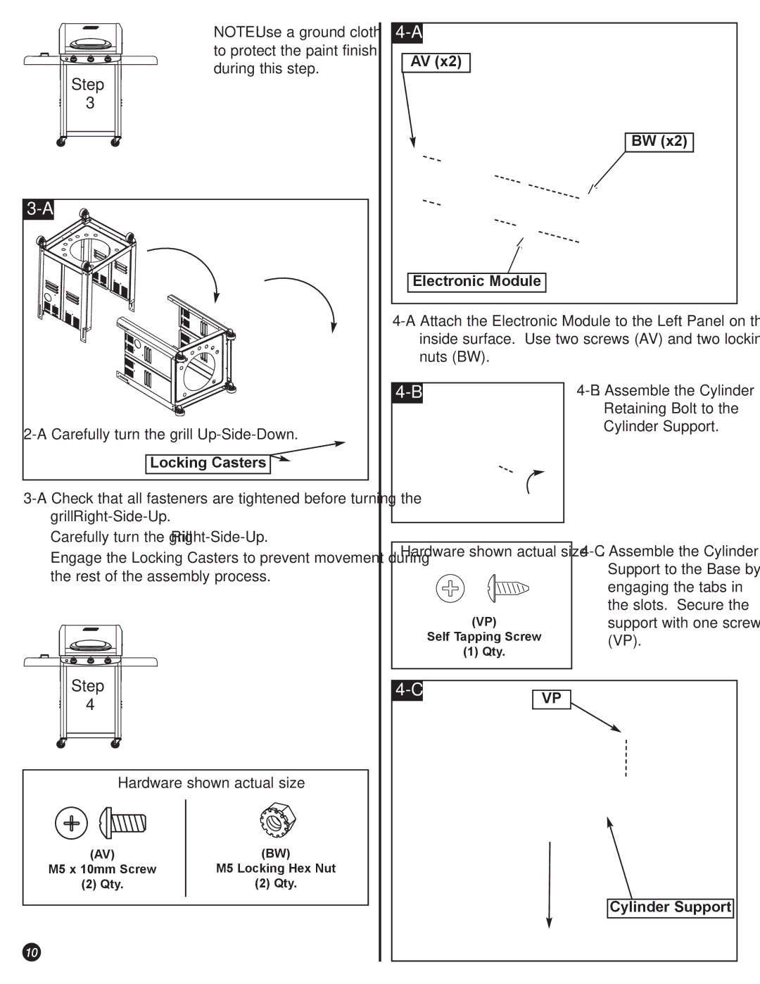
Ö NOTE: Use a ground cloth to protect the paint finish during this step.
AV (x2) |
BW (x2) |
Electronic Module |
Locking Casters 
ÖCarefully turn the grill
ÖEngage the Locking Casters to prevent movement during the rest of the assembly process.
Step
4
Hardware shown actual size
(AV) | (BW) |
M5 x 10mm Screw | M5 Locking Hex Nut |
(2) Qty. | (2) Qty. |
|
|
10
| ||
|
| Retaining Bolt to the |
|
| |
|
| Cylinder Support. |
|
|
|
Hardware shown actual size | |
| Support to the Base by |
| engaging the tabs in |
| the slots. Secure the |
(VP) | support with one screw |
Self Tapping Screw | (VP). |
(1) Qty. |
|
|
|
VP | |
|
