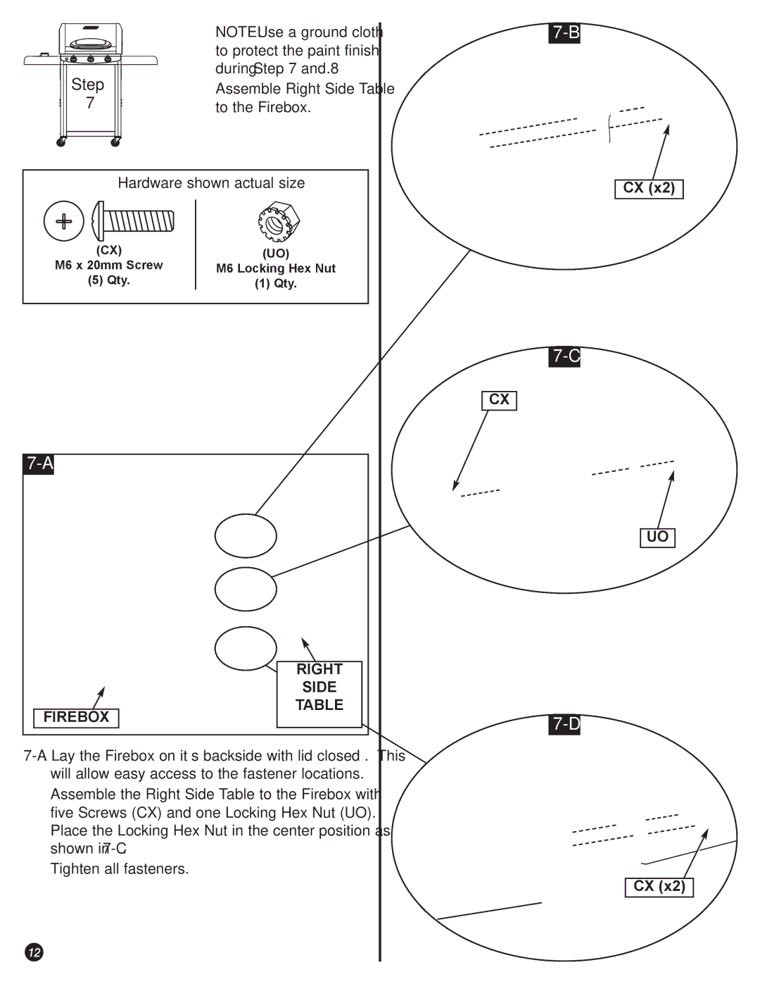
| Ö | NOTE: Use a ground cloth |
|
| to protect the paint finish |
Step |
| during Step 7 and 8. |
Ö | Assemble Right Side Table | |
7 |
| to the Firebox. |
Hardware shown actual size
(CX) | (UO) |
M6 x 20mm Screw | M6 Locking Hex Nut |
(5) Qty. | (1) Qty. |
CX (x2)
CX
FIREBOX
RIGHT
SIDE
TABLE
UO
ÖAssemble the Right Side Table to the Firebox with five Screws (CX) and one Locking Hex Nut (UO). Place the Locking Hex Nut in the center position as shown in
ÖTighten all fasteners.
12
CX (x2)
