Step
15
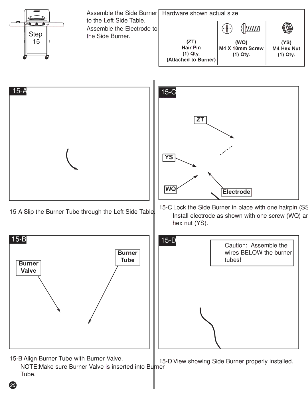
ÖAssemble the Side Burner to the Left Side Table.
ÖAssemble the Electrode to the Side Burner.
Hardware shown actual size
(ZT) | (WQ) | (YS) |
Hair Pin | M4 X 10mm Screw | M4 Hex Nut |
(1) Qty. | (1) Qty. | (1) Qty. |
(Attached to Burner)
15-A
15-B
Burner
15-C
ZT
YS
WQElectrode
ÖInstall electrode as shown with one screw (WQ) and one hex nut (YS).
15-D
Caution: Assemble the wires BELOW the burner
Burner
Valve
Tube
tubes!
ÖNOTE: Make sure Burner Valve is inserted into Burner Tube.
20