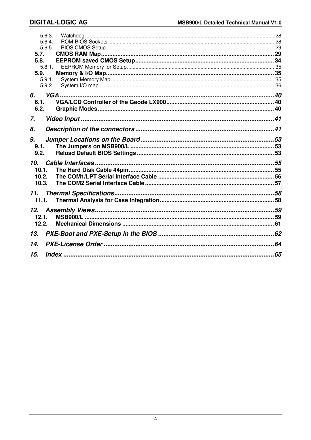
MSB900, MSB900L specifications
The Compaq MSB900 and MSB900L are noteworthy entries in the realm of personal computing, particularly for their cutting-edge features and innovative technologies that defined their era. Positioned as versatile desktop solutions, both models have garnered attention for their robust performance and user-friendly design.The Compaq MSB900 is equipped with a powerful processor that enhances multitasking efficiency. Its architecture supports a range of demanding applications, making it suitable for both professional and everyday use. Users can expect a seamless experience whether working on complex spreadsheets or engaging in casual gaming.
In terms of memory, the MSB900 boasts expandable RAM options, allowing users to enhance their system's capabilities as needed. The availability of multiple RAM slots provides flexibility for upgrades, ensuring the system can keep pace with future software requirements. Storage solutions in the MSB900 include high-speed hard drives, which contribute to fast boot times and robust data retrieval.
The MSB900L variant steps up the performance with additional features tailored for power users. It incorporates advanced graphics capabilities, offering superior visual experiences for gaming and multimedia applications. The dedicated graphics card provides a substantial boost in rendering performance, making it a worthy choice for graphic designers and video editors.
One of the standout characteristics of the MSB900 and MSB900L is their commitment to connectivity. Both models come equipped with a wide array of ports, ensuring compatibility with various peripherals. This includes USB ports for modern devices, Ethernet ports for wired networking, and legacy connections for older technology, catering to a diverse user base.
Energy efficiency is another key feature of these models. Designed with power-saving technologies, the Compaq MSB900 and MSB900L aim to reduce energy consumption without compromising performance. This focus not only helps to lower operating costs but also aligns with growing consumer preferences for environmentally conscious products.
In summary, the Compaq MSB900 and MSB900L offer a compelling combination of performance, expandability, and connectivity. Their innovative features and user-friendly design make them suitable for a wide range of users, from casual consumers to professional power users. As a testament to Compaq’s legacy, these models continue to be regarded as reliable choices in the personal computing landscape.
