Chapter 2 Hardware Configuration
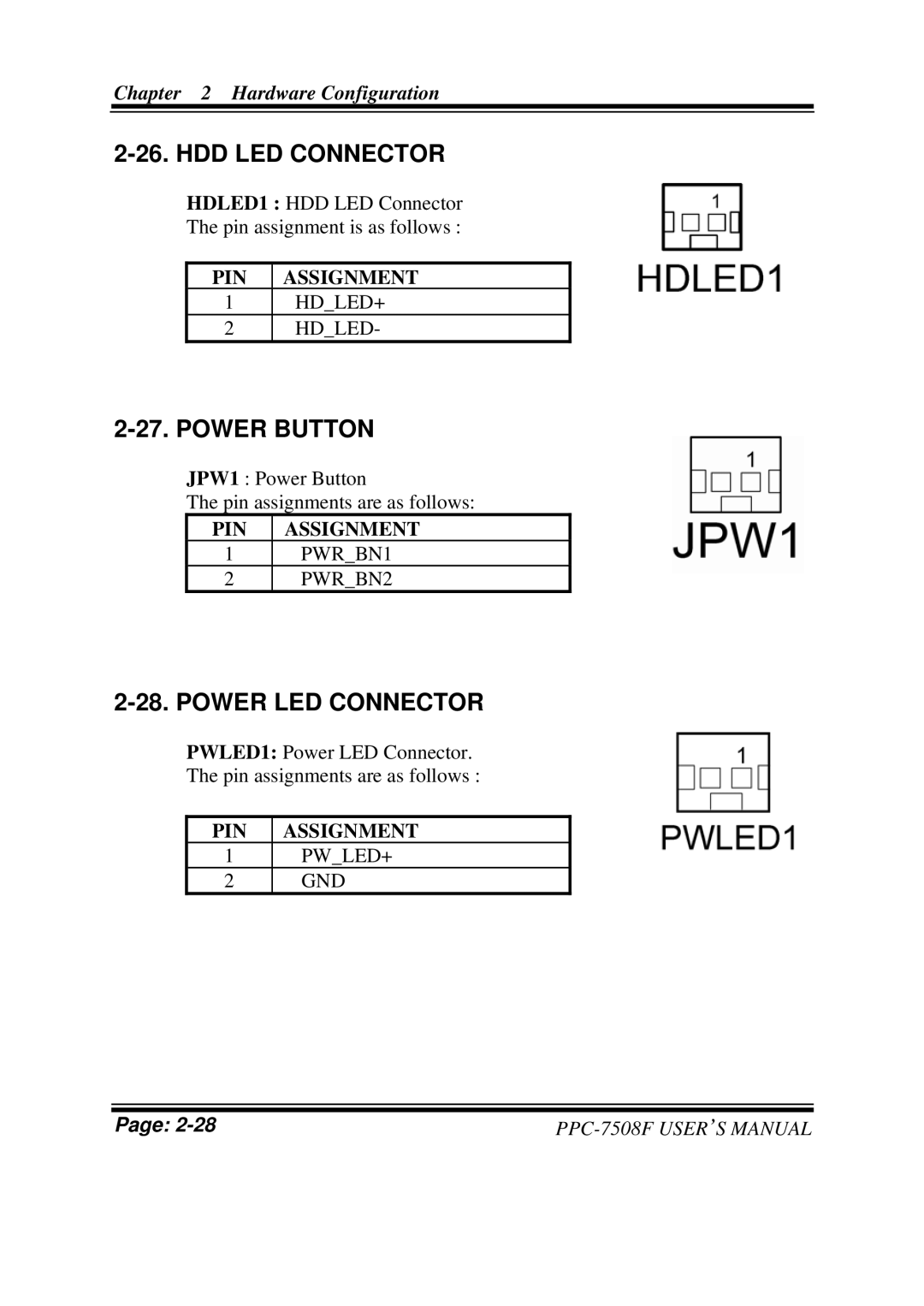
2-26. HDD LED CONNECTOR
HDLED1 : HDD LED Connector
The pin assignment is as follows :
PIN ASSIGNMENT
1HD_LED+
2HD_LED-
2-27. POWER BUTTON
JPW1 : Power Button
The pin assignments are as follows:
PIN ASSIGNMENT
1PWR_BN1
2PWR_BN2
2-28. POWER LED CONNECTOR
PWLED1: Power LED Connector.
The pin assignments are as follows :
PIN ASSIGNMENT
1PW_LED+
2GND
Page: |