| SMA200 Manual V1.0 |
3.3.Connector Placement & Pin Definition on the Carrier Board
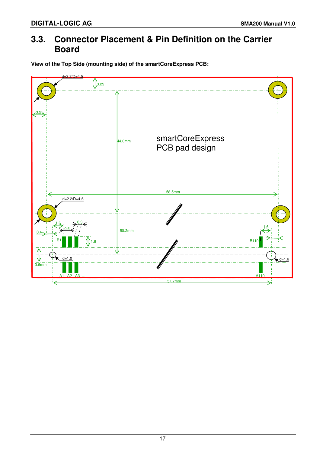
View of the Top Side (mounting side) of the smartCoreExpress PCB:
d=2.2/D=4.5
3.25
3.25
44.0mmsmartCoreExpress PCB pad design
|
| 58.5mm |
d=2.2/D=4.5 |
| |
1.6 | 0.3 |
|
0.5 |
| 1.6 |
| 50.2mm | |
0.4 |
| |
|
| |
B1 | 1.8 | B110 |
d=1.0 |
| d=1.6 |
3.6mm |
|
|
A1 A2 | A3 ... | A110 |
|
| 57.7mm |
17