| SMA200 Manual V1.0 |
5.4.11.SATA Interface (Option)
|
|
|
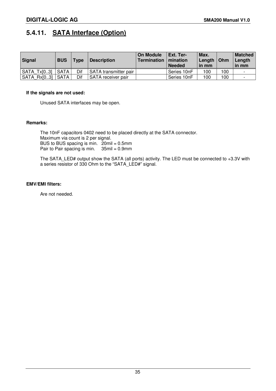
| On Module | Ext. Ter- | Max. |
| Matched |
Signal | BUS | Type | Description | Termination | mination | Length | Ohm | Length |
|
|
|
|
| Needed | in mm |
| in mm |
SATA_Tx[0..3] SATA SATA_Rx[0..3] SATA
Dif Dif
SATA transmitter pair SATA receiver pair
Series 10nF Series 10nF
100
100
100
100
-
-
If the signals are not used:
Unused SATA interfaces may be open.
Remarks:
The 10nF capacitors 0402 need to be placed directly at the SATA connector.
Maximum via count is 2 per signal.
BUS to BUS spacing is min. 20mil = 0.5mm
Pair to Pair spacing is min. 35mil = 0.9mm
The SATA_LED# output show the SATA (all ports) activity. The LED must be connected to +3.3V with a series resistor of 330 Ohm to the “SATA_LED#” signal.
EMV/EMI filters:
Are not needed.
35
