TECHNICAL USER MANUAL FOR:
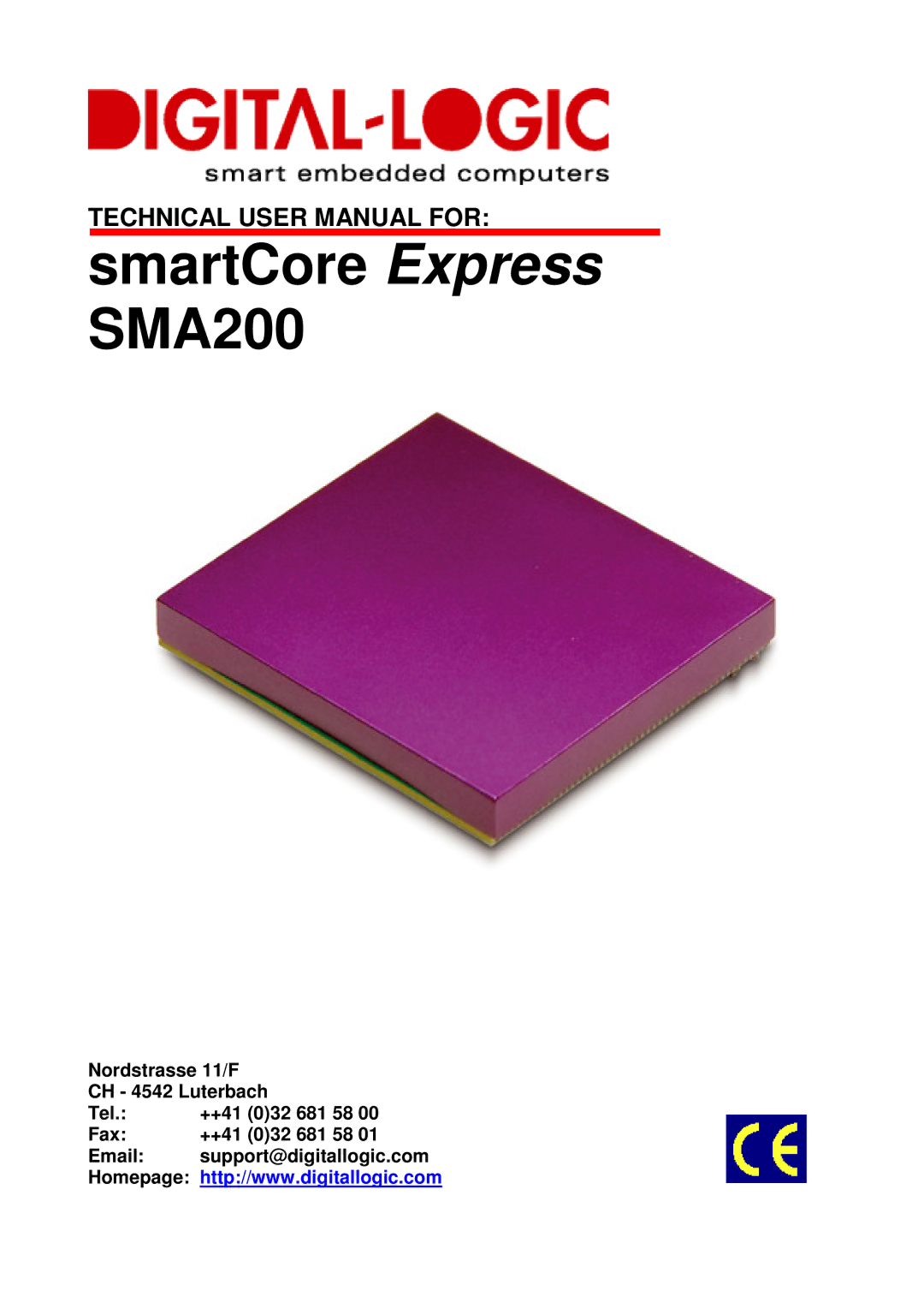
smartCore Express SMA200
Nordstrasse 11/F
CH - 4542 Luterbach
Tel.: | ++41 (0)32 681 58 00 |
Fax: | ++41 (0)32 681 58 01 |
Email: | support@digitallogic.com |
Homepage: | http://www.digitallogic.com |
TECHNICAL USER MANUAL FOR:
Nordstrasse 11/F
CH - 4542 Luterbach
Tel.: | ++41 (0)32 681 58 00 |
Fax: | ++41 (0)32 681 58 01 |
Email: | support@digitallogic.com |
Homepage: | http://www.digitallogic.com |