Intel Pentium 4 Processor and the 845 Chipset
Technical Reference Guide
Page
TRG
Page
Featuring the Intel Pentium 4 Processor
Second Edition -- January
Table of Contents
System Support
Power Supply and Distribution
Appendix B Ascii Character SET
Appendix D COMPAQ/NVIDIA Vanta LT AGP Graphics Card
Technical Reference Guide
List of Figures
Power Distribution and CONTROL, Block Diagram
List of Tables
Technical Reference Guide
Table H-2
This page is intentionally blank
Hardcopy
About this Guide
Online Viewing
XXX/XNN/NN/N/NNNx
Additional Information Sources
Model Numbering Convention
Serial Number
Register Notation and Usage
Notational Conventions
Values
Ranges
Acronym/Abbreviation Description
Common Acronyms and Abbreviations
Acronyms and Abbreviations
DDR
DAC
DCH
DDC
ISA
INT
IPL
IRQ
Post
PFC
PIN
PIO
TFT
TAD
Tafi
TCP
Introduction
System Overview
Configurable
Features and Options
Standard Features
Feature Difference Matrix by Form Factor
Options
Mechanical Design
Evo or Workstation Small Form Factor
Cabinet Layouts
Front Views
Compaq Evos and Workstation, Rear Views
Rear Views
Front
Chassis Layouts
Back
Desktop Chassis Layout, Top View
AGP Slot PCI Slot Drive Lock
Small Form Factor Board Layouts
Board Layouts
Desktop or Configurable Minitower Main Board Layouts
SDR SDR/DDR
Desktop Configurable Minitower
System Architecture
FWH
RGB AGP
AGP Sdram
ICH2 USB LPC
Intel Pentium 4 Processor
10.Processor Assembly And Mounting
Support Component Functions
Chipset
Support Components
Chipset Functions
Universal Serial BUS Interface
System Memory
Mass Storage
Serial and Parallel Interfaces
NVIDIA Matrox
Graphics Subsystem
Standard AGP Graphics Comparison
Audio Subsystem
Specifications
Environmental Specifications Factory Configuration
Electrical Specifications
Compaq SP#
Physical Specifications
Diskette Drive Specifications
Small Configurable Parameter
CD-R, CD-RW
Optical Drive Specifications
Hard Drive Specifications
Parameter 48x CD-ROM 16/10/40x CD-RW Drive
XMM1 XMM2 XMM3 Dimm
FSB I/F
AGP MCH
Processor Overview
Pentium 4 Processor
FSB
CPU FPU
Processor Upgrading
Memory Subsystem
Dimm ID
SPD Address Map Sdram Dimm
Byte Description
Shows the system memory map
PCI Config Reset Addr Register Value
Subsystem Configuration
Host/PCI Bridge Configuration Registers GMCH, Device
System Support
Eide USB
PCI BUS Overview
PCI Bus Devices and Functions
1.1 I/O and Memory Cycles
Configuration Cycles
PCI BUS Transactions
Device #
PCI Component Configuration Access
Idsel
PCI Component
PCI Device Vendor ID Device ID
PCI Configuration Space Type
System Board PCI Device Identification
Bist
REQ/GNT Line Device
PCI BUS Master Arbitration
PCI Bus Mastering Devices
PCI SUB-BUSSES
PCI Power Management Support
Option ROM Mapping
PCI Interrupts
Addr Value Register
PCI Configuration
LPC Bridge Configuration Registers ICH2, Function 0, Device
Config Register Reset
Pin Signal
PCI Connector
PCI Bus Connector Pinout
BUS Transactions
AGP BUS Overview
CLK D1A D1B D2A D2B GNT Trdy
Data Request
Data Transfers
GNT Trdy
CLK D1A D1B D2A D2B D3A D3B D4A D4B
Config Reset Addr Register Value
AGP Configuration
VDD
AGP Connector
AGP Bus Connector Pinout
Ovrcnt GND VDD3
Maskable Interrupts
System Resources
Interrupts
Maskable Interrupt Priorities and Assignments
Apic Mode
Priority Signal Label Source Typical
Mode
Port Register
Non-Maskable Interrupts
NMI- Generation
Maskable Interrupt Control Registers
IOCHK- NMI
SMI- Generation
DMA Channel Device ID
Direct Memory Access
Default DMA Channel Assignments
DMA Channel Register I/O Port
DMA Page Registers
DMA Page Register Addresses
Register Controller
DMA Controller Registers
DMA Controller Registers
Frequncy Source Destination
System Clock Distribution
Clock Generation and Distribution
Clearing Cmos
REAL-TIME Clock and Configuration Memory
Location Function
Cmos Archive and Restore
Configuration Memory Cmos Map
Standard Cmos Locations
Security Functions
Power-On Password
Setup Password
System Management
Chassis Security
Cable Lock Provision
1.4 I/O Interface Security
Acpi Wake-Up Event System Wakes From
Power Management
System Boot/ROM Flash Status LED Indications
System Status
System Operational Status LED Indications
Power Hard Drive System Status
Thermal Sensing and Cooling
11.Small Form Factor Fan Control Block Diagram
Port Function
Register MAP and Miscellaneous Functions
System I/O MAP
System I/O Map
LPC47B367 I/O Controller Control Registers
Index Function Reset Value
2 LPC47B367 I/O Controller Functions
HD LED
System Status Power LED
IDE Programming
Enhanced IDE Interface
IDE Bus Master Control Registers
IDE Configuration Registers
Eide PCI Configuration Registers 82801, Device 31/Function
IDE Bus Master Control Registers
Pin Signal Description
IDE Connector
Pin Primary IDE Connector Pinout
Diskette Drive Interface
Diskette Drive Programming
Diskette Drive Interface Configuration
Diskette Drive Interface Configuration Registers
Index Reset
Pri
Diskette Drive Interface Control Registers
Pin Diskette Drive Connector Pinout
Diskette Drive Connector
Serial Interface
Serial Connector
DB-9 Serial Connector Pinout
Function
Serial Interface Configuration
Serial Interface Configuration Registers
Serial Interface Programming
Addr Register
Serial Interface Control
Serial Interface Control Registers
Parallel Interface
Standard Parallel Port Mode
Extended Capabilities Port Mode
Enhanced Parallel Port Mode
Parallel Interface Programming
Parallel Interface Configuration
Parallel Interface Configuration Registers
Address Register
Parallel Interface Control
Parallel Interface Control Registers
Pin Signal Function
Parallel Interface Connector
DB-25 Parallel Connector Pinout
Keyboard Interface Operation
KEYBOARD/POINTING Device Interface
Command
To-Keyboard Commands
KEYBOARD/POINTING Device Interface Programming
3.1 8042 Configuration
Keyboard Interface Configuration Registers
Pointing Device Interface Operation
Port 60h
3.2 8042 Control
Value Command Description
CPU Commands To
Data
KEYBOARD/POINTING Device Interface Connector
Keyboard/Pointing Device Connector Pinout
USB Data Formats
USB I/F, Block Diagram
CRC
USB Control
USB Configuration
USB Interface Configuration Registers
USB Programming
USB Cable Length Data
USB Connector
USB Connector Pinout
USB Cable Data
Functional Analysis
CD ROM
Front Panel Assembly
TDA
SD OUT
2 AC97 Audio Controller
3 AC97 Link BUS
Sync
PB Data R
Audio Codec
AC’97 Audio Codec Control Registers
Audio Configuration
Audio Programming
Audio Control
Paramemter
Audio Specifications
AC97 Audio Subsystem Specifications
TX/RX
TX/RX LAN PHY I/F
Event Description
Wake on LAN Support
Alert on LAN Support
AOL Events
Acpi Environment
Power Management Support
APM Environment
NIC Control Registers
Configuration
NIC Programming
Control
MS-DOS
NIC Connector
NIC Specifications
NIC Specifications
SOS PCI
NIC UPGRADING/CHANGING
AOL/SOS
Asic PCI
Remote System Alert Events
AUX
Power Supply ASSEMBLY/CONTROL
Range Min. Current Max Surge
Power Supply Assembly
Watt Power Supply Assembly Specifications PN
System State Pressed Power Button Results
Power Control
Power Button
Wake Up Events
Power LED Indications
Power LED Condition
Power Transition OS Restart State System Condition
System Power States
RTN
Power Distribution
1 3.3/5/12 VDC Distribution
Conn Pin
Desktop and Configurable Minitower Power Cable Diagram
AGP PWR DDR
LOW Voltage PRODUCTION/DISTRIBUTION
VID0 VID1 VID2
VID4
IDE I/F CD-ROM
Signal Distribution
System Board
System
Desktop/Minitower Signal Distribution Diagram
AOL/SOS Header P12
Power Button/LED Header P5
CD ROM Audio Header P7
This page is intentionally blank
Bios ROM
Num Lock Cap Lock Scroll Lock
Boot Block Codes
ROM Flashing
Upgrading
\Flashi.exe ImageFilename BackgroundColor ForegroundColor
Changeable Splash Screen
Network Boot F12 Support
Boot Functions
Boot Device Order
Visual Audible Meaning
Memory Detection and Configuration
Boot Error Codes
Boot Error Codes
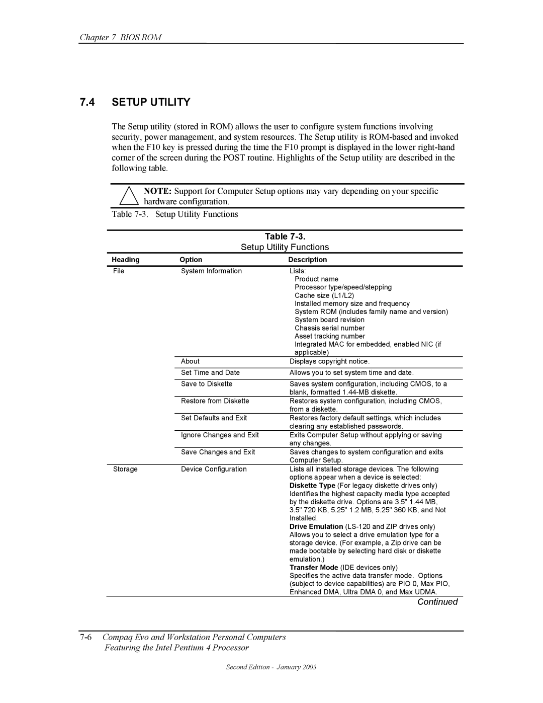
Heading Option Description
Setup Utility
Setup Utility Functions
Multisector Transfers IDE ATA devices only
Translation Mode IDE disks only
Removable Media Boot
Translation Parameters IDE Disks only
CTRL+ALT+DEL
Heading Option Description
Setup Utility Functions
Setup Utility Functions
Setup Utility Functions
Client Management Functions INT15
Function Mode
Client Management Functions
ECX
Input EAX
Output
EBX
System System ID ROM Family PnP ID
System ID and ROM Type
Edid Retrieve
PNP Support
Temperature Status
Drive Fault Prediction
PnP Bios Functions
Smbios
Independent PM Support
Power Management Functions
System Timer
IDE Hard Drive Timer
Suspend
Going to Sleep in Independent PM
System Standby
IDE Hard Drive Standby
APM 1.2 Support
Acpi Support
APM Bios Function Description
APM Bios Functions
Staying Awake in APM
System Suspend
Going to Sleep in APM
System/Hard Drive Standby
USB Legacy Support
Waking Up in APM
This page is intentionally blank
Beeps LED Probable Cause
BEEP/KEYBOARD LED Codes
Table A-1
Beep/Keyboard LED Codes
Table A-2
POWER-ON Self Test Post Messages
Power-On Self Test Post Messages
Error Message Probable Cause
Message Probable Cause
System Error Messages
System Error Messages
Table A-3
Table A-5
Memory Error Messages
Keyboard Error Messages
Table A-4
Table A-7
Printer Error Messages
Video Graphics Error Messages
Table A-6
Table A-9
Diskette Drive Error Messages
Serial Interface Error Messages
Table A-8
Table A-10
Modem Communications Error Messages
Table A-12
System Status Error Messages
Hard Drive Error Messages
Table A-11
Table A-14
Table A-13
Network Interface Error Messages
Audio Error Messages
17 DVD/CD-ROM Error Messages
Table A-19
Scsi Interface Error Messages 65xx-xx, 66xx-xx
Pointing Device Interface Error Messages
Table A-18
12Compaq Personal Computers
Dec Hex
Symbol Dec Hex
Table B-1
Ascii Character Set
Table B-1.ASCII Code Set
Dec Hex Symbol
Keyboard
Keystroke Processing
Parameter Minimum Nominal Maximum
1 PS/2-TYPE Keyboard Transmissions
USB-TYPE Keyboard Transmissions
Standard Enhanced Keyboards
Keyboard Layouts
Figure C-6.National Windows 102W-Key Keyboard Key Positions
Windows Enhanced Keyboards
Figure C-8.8-Button Easy Access Keyboard Layout
Easy Access Keyboards
Special Single-Keystroke Functions
Keys
Windows Keystrokes
Multi-Keystroke Functions
Button # Description Default Function
Easy Access Keystrokes
Scan Codes
Keyboard Commands
Keyboard-to-System Commands
Command
Mode
Table C-2
Keyboard Scan Codes
Key Make / Break Codes Hex Pos
Table C-2. Keyboard Scan Codes
7E/FE
Key
Table C-2. Keyboard Scan Codes
Pin
Connectors
Sdram Nvidia
COMPAQ/NVIDIA Vanta LT AGP Graphics Card
Functional Description
Nvidia Vanta LT Display Modes
Resolution Bits per pixel Color Depth
Display Modes
Software Support Information
Power Management and Consumption
Monitor Power Management Conditions
SCL
Monitor Connector
DB-15 Monitor Connector Pinout
SDA
6Compaq Personal Computers
COMPAQ/NVIDIA QUADRO2 EX/MXR AGP Graphics Cards
Appendix E Compaq/NVIDIA Quadro2 EX/MXR AGP Graphics Cards
Nvidia Quadro2 EX/MXR Graphics Display Modes
Resolution Bits per pixel Color Depth
Table E-1
Table E-2
Monitor Power Management Conditions
Table E-3
DB-15 Monitor Connector Pinout
Pin Signal Description
6Compaq Personal Computers
Appendix F COMPAQ/Matrox Millennium G450
Appendix H Compaq/Matrox Millennium G450 AGP Graphics Card
Matrox Millennium G450 Graphics Display Modes
Table F-1
Table F-2
Table F-3
Table F-4
Video Feature Connector
Video In Connector Pinout
COMPAQ/ADAPTEC 29160N Scsi Host Adapter
Appendix G Compaq/Adaptec 29160N Scsi Host Adapter
Table G-2
Scsi Adapter Programming Scsi Adapter Configuration
Scsi Adapter Control
Table G-1
Pin Signal Function
Scsi Connectors
External 50-PIN Ultra Scsi Connector
External Ultra Scsi Connector Pinout
Table G-4
Internal 50-PIN Ultra Scsi Connector
Internal 50-Pin Ultra Scsi Connector Pinout
Table G-5
Internal 68-PIN ULTRA160 Scsi Connector
Ultra160 Scsi Connector Pinout
PCI Graphics Card
DVI RGB
Card Edge Connector
Matrox G200 MMS Graphics Controller Display Modes
Table H-1
MULTI-CARD Configuration with Windows NT
Display Configuration SINGLE-CARD Configuration
Table H-2
Pin Description
Adapter Cable Connector
Adapter Cable Connector Pinout
Table H-3
Table H-4
Analog Monitor Connector
DVI-D Connector Pinout
Digital Monitor Connector
10Compaq Personal Computers
Dimm support
Index
ROM Bios
Physical
Specifications
Electrical
Environmental
This page is intentionally blank