Appendix B - Connector and Cable Pin Outs | 35 |
Appendix B - Connector and Cable Pin Outs
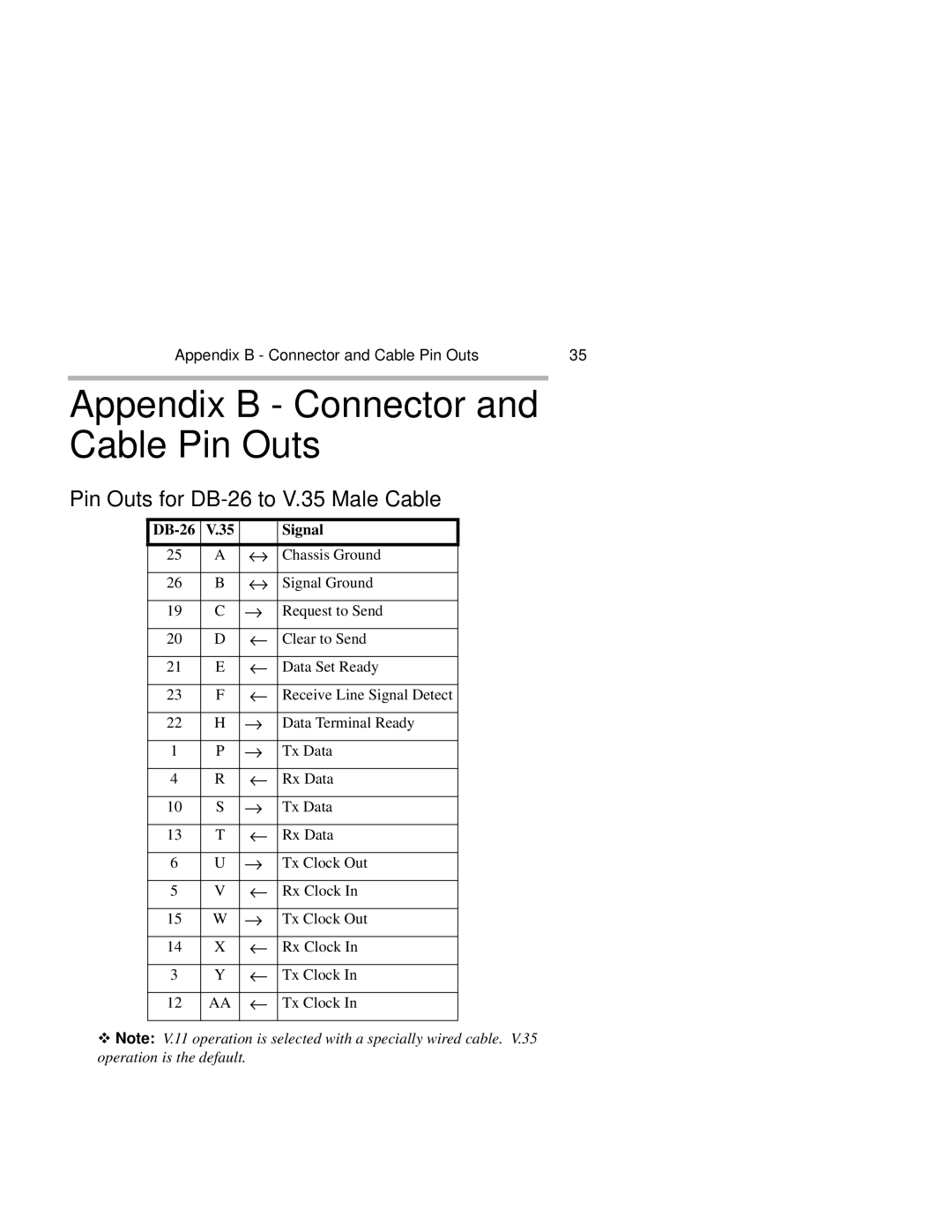
Pin Outs for DB-26 to V.35 Male Cable
| V.35 |
| Signal |
|
|
|
|
25 | A | ↔ | Chassis Ground |
26 | B | ↔ | Signal Ground |
|
|
|
|
19 | C | → | Request to Send |
|
|
|
|
20 | D | ← | Clear to Send |
|
|
|
|
21 | E | ← | Data Set Ready |
|
|
|
|
23 | F | ← | Receive Line Signal Detect |
|
|
|
|
22 | H | → | Data Terminal Ready |
|
|
|
|
1 | P | → | Tx Data |
|
|
|
|
4 | R | ← | Rx Data |
|
|
|
|
10 | S | → | Tx Data |
|
|
|
|
13 | T | ← | Rx Data |
|
|
|
|
6 | U | → | Tx Clock Out |
|
|
|
|
5 | V | ← | Rx Clock In |
|
|
|
|
15 | W | → | Tx Clock Out |
|
|
|
|
14 | X | ← | Rx Clock In |
|
|
|
|
3 | Y | ← | Tx Clock In |
|
|
|
|
12 | AA | ← | Tx Clock In |
|
|
|
|
ϖNote: V.11 operation is selected with a specially wired cable. V.35 operation is the default.