3.

Montage et connections

3.

Mounting and Connections

3.1Montage murale

Utiliser le plan de forage inclus pour placer les trous du support. Enlever le support du transmetteur.

3.2Branchement du transmetteur

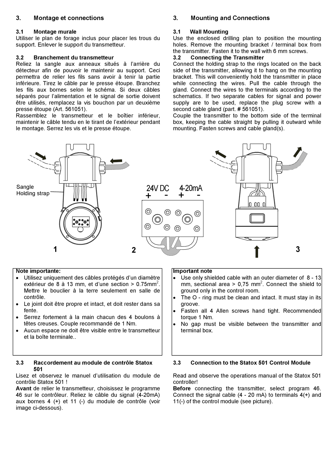
Reliez la sangle aux anneaux situés à l’arrière du détecteur afin de pouvoir le maintenir au support. Ceci permettra de relier les fils sans avoir à tenir la partie inférieure. Tirez le câble par le presse étoupe. Branchez les fils aux bornes selon le schéma. Si deux câbles séparés pour l’alimentation et le signal de sortie doivent être utilisés, remplacez la vis bouchon par un deuxième presse étoupe (Art. 561051).

Rassemblez le transmetteur et le boîtier inférieur, maintenir le câble tendu en le tirant de l’extérieur pendant le montage. Serrez les vis et le presse étoupe.

3.1Wall Mounting

Use the enclosed drilling plan to position the mounting holes. Remove the mounting bracket / terminal box from the transmitter. Fasten it to the wall with 6 mm screws.

3.2Connecting the Transmitter

Connect the holding strap to the rings located on the back side of the transmitter, allowing it to hang on the mounting bracket. This will conveniently hold the transmitter in place while connecting the wires. Pull the cable through the gland. Connect the wires to the terminals according to the schematics. If two separate cables for signal and power supply are to be used, replace the plug screw with a second cable gland (part. # 561051).

Couple the transmitter to the bottom side of the terminal box, keeping the cable straight by pulling it outward while mounting. Fasten screws and cable gland(s).

Sangle Holding strap

24V DC

4-20mA

+

-

+

-


12

Note importante:

Utilisez uniquement des câbles protégés d’un diamètre extérieur de 8 à 13 mm, et d’une section > 0.75mm2. Mettre le bouclier à la terre seulement en salle de contrôle.

Le joint doit être propre et intact, et doit rester dans sa fente.

Serrez fortement à la main chacun des 4 boulons à têtes creuses. Couple recommandé de 1 Nm.

Aucun espace ne doit être visible entre le transmetteur et la boîte terminale..

3.3Raccordement au module de contrôle Statox

501

Lisez et observez le manuel d’utilisation du module de contrôle Statox 501 !

Avant de relier le transmetteur, choisissez le programme 46 sur le contrôleur. Reliez le câble du signal (4-20mA) aux bornes 4 (+) et 11 (-) du module de contrôle (voir image ci-dessous).

3

Important note

Use only shielded cable with an outer diameter of 8 - 13 mm, sectional area > 0,75 mm2. Connect the shield to ground only in the control room.

The O - ring must be clean and intact. It must stay in its groove.

Fasten all 4 Allen screws hand tight. Recommended torque 1 Nm.

No gap must be visible between the transmitter and terminal box.

3.3Connection to the Statox 501 Control Module

Read and observe the operations manual of the Statox 501 controller!

Before connecting the transmitter, select program 46. Connect the signal cable (4 - 20 mA) to terminals 4(+) and 11(-) of the control module (see picture).

Page 4
Image 4
Compur 501 IR manual Montage et connections

501 IR specifications

The Compur 501 IR is an advanced infrared gas analyzer focused on the detection and measurement of trace gases in various applications. Renowned for its precision and reliability, the Compur 501 IR provides a comprehensive solution to industries requiring data on gases such as carbon dioxide, methane, and volatile organic compounds. This state-of-the-art instrument is vital for environmental monitoring, industrial processes, and safety compliance.

One of the standout features of the Compur 501 IR is its dual-beam infrared absorption technology. This technology enhances measurement accuracy by minimizing errors that can arise from variations in temperature and pressure. The dual-beam setup allows for continuous measurement of gas concentrations, providing real-time data crucial for process control and environmental analysis. The analyzer's sensitivity enables it to detect even the slightest changes in gas concentrations, ensuring operators are alert to any potential hazardous conditions.

The Compur 501 IR is equipped with a sophisticated microprocessor-based system that facilitates user-friendly operations. The intuitive interface allows users to configure settings, view measurements, and access calibration features with ease. Additionally, the analyzer supports various communication protocols, enabling seamless integration with existing data management systems, which is critical for efficient operation and record-keeping.

In terms of durability, the Compur 501 IR boasts robust construction designed to withstand harsh operating conditions. It features a rugged enclosure that protects sensitive components from dust, moisture, and physical impact, ensuring consistent performance in challenging environments. Moreover, the device is engineered for low maintenance, with long-lasting components that reduce the need for frequent servicing.

Another key characteristic of the Compur 501 IR is its adaptability to different calibration standards. This flexibility makes it suitable for a wide range of applications, from industrial emissions monitoring to indoor air quality assessment. The capability to customize calibration settings allows the analyzer to meet specific regulatory requirements, ensuring compliance with environmental standards.

Overall, the Compur 501 IR stands out for its innovative technology, exceptional accuracy, and user-centric design. Its ability to deliver precise gas measurements in real time is invaluable for industries focused on safety, regulation, and environmental stewardship. This advanced gas analyzer exemplifies the forefront of gas detection technology, making it a reliable choice for professionals across multiple sectors.