Brick™ Fuses 1025F Series Fast Acting, Low Breaking Capacity
Description
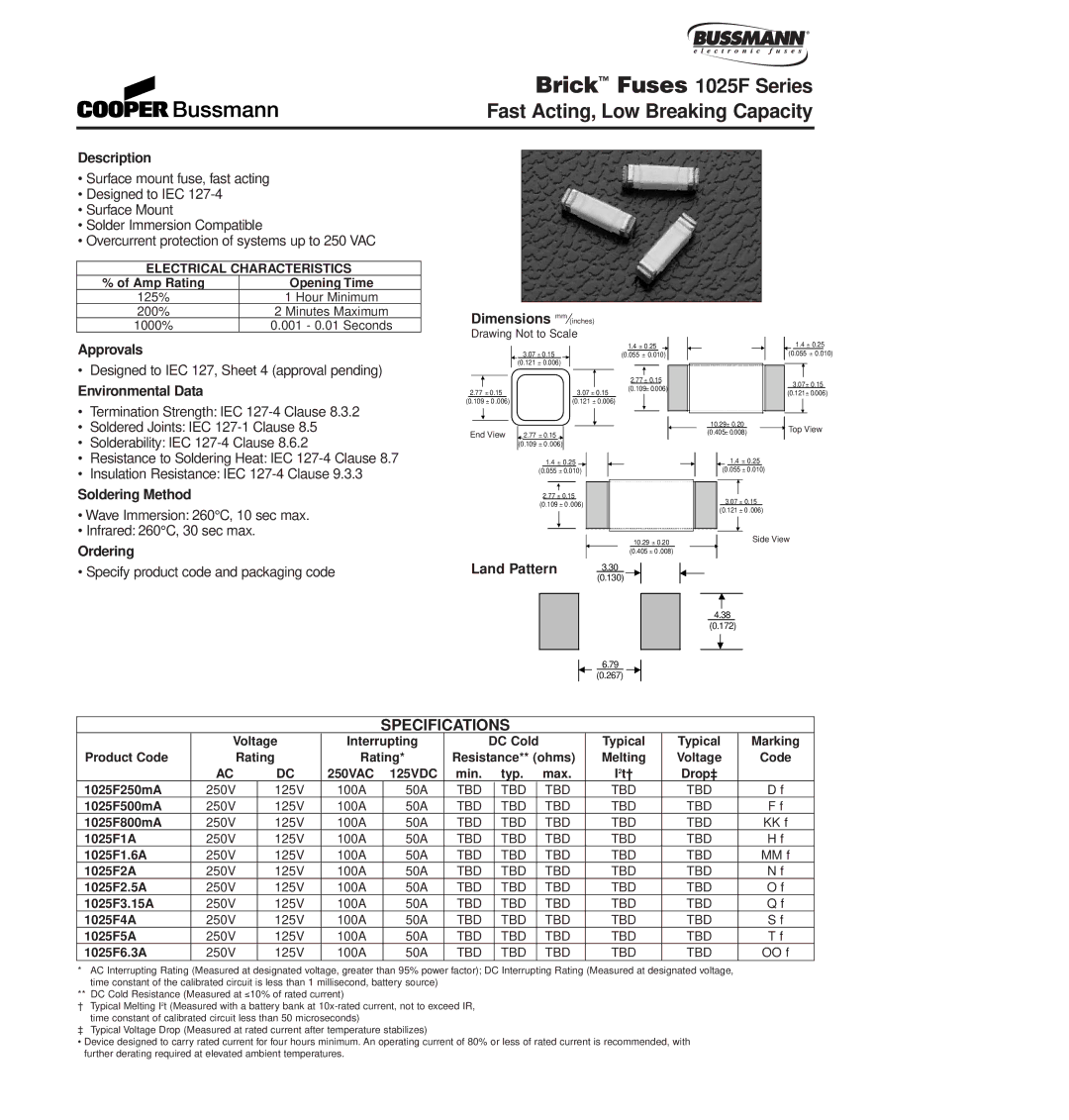
•Surface mount fuse, fast acting
•Designed to IEC
•Surface Mount
•Solder Immersion Compatible
•Overcurrent protection of systems up to 250 VAC
ELECTRICAL CHARACTERISTICS
% of Amp Rating | Opening Time |
125% | 1 Hour Minimum |
200% | 2 Minutes Maximum |
1000% | 0.001 - 0.01 Seconds |
Approvals
• Designed to IEC 127, Sheet 4 (approval pending)
Environmental Data
•Termination Strength: IEC
•Soldered Joints: IEC 127-1 Clause 8.5
•Solderability: IEC
•Resistance to Soldering Heat: IEC
•Insulation Resistance: IEC
Soldering Method
•Wave Immersion: 260°C, 10 sec max.
•Infrared: 260°C, 30 sec max.
Ordering
• Specify product code and packaging code
Dimensions mm⁄(inches)
Drawing Not to Scale
|
|
|
|
|
|
| 3.07 ± 0.15 |
|
|
|
|
|
|
|
|
|
|
|
|
|
|
| 1.4 ± 0.25 |
|
|
|
|
| |||||||
|
|
|
|
|
|
|
|
|
|
|
|
|
|
|
|
|
|
|
|
|
| (0.055 ± 0.010) |
|
|
|
| |||||||||
|
|
|
|
|
|
| (0.121 ± 0.006) |
|
|
|
|
|
|
|
|
|
|
|
|
|
|
|
|
|
|
|
|
|
|
| |||||
|
|
|
|
|
|
|
|
|
|
|
|
|
|
|
|
|
|
|
|
|
|
|
|
|
|
|
|
|
|
|
|
|
|
|
|
|
|
|
|
|
|
|
|
|
|
|
|
|
|
|
|
|
|
|
|
|
|
|
|
|
| 2.77 ± 0.15 |
|
|
|
| |||||
|
|
|
|
|
|
|
|
|
|
|
|
|
|
|
|
|
|
|
|
|
|
|
|
|
|
|
|
|
|
|
|
| |||
| 2.77 ± 0.15 |
|
|
|
| 3.07 | ± 0.15 |
|
| (0.109± 0.006) |
|
|
|
| |||||||||||||||||||||
|
|
|
|
|
|
|
|
|
|
|
|
|
|
| |||||||||||||||||||||
(0.109 ± 0 .006) |
| (0.121 ± 0.006) |
|
|
|
|
|
|
|
|
|
| |||||||||||||||||||||||
|
|
|
|
|
|
|
|
|
|
|
|
|
|
|
|
|
|
|
|
|
|
|
|
|
|
|
|
|
|
|
|
|
|
|
|
|
|
|
|
|
|
|
|
|
|
|
|
|
|
|
|
|
|
|
|
|
|
|
|
|
|
|
|
|
|
|
|
|
|
|
|
| End View |
| 2.77 ± 0.15 |
|
|
|
|
|
|
|
|
|
|
|
|
|
|
|
|
|
|
|
|
|
|
|
|
| |||||||
|
|
|
|
|
|
| (0.109 ± 0 .006) |
|
|
|
|
|
|
|
|
|
|
|
|
|
|
|
|
|
|
|
|
|
|
| |||||
|
|
|
|
|
|
|
| 1.4 ± 0.25 |
|
|
|
|
|
|
|
|
|
|
|
|
|
|
|
|
|
|
| ||||||||
|
|
|
|
|
|
|
|
|
|
|
|
|
|
|
|
|
|
|
|
|
|
|
|
|
| ||||||||||
|
|
|
|
|
|
|
|
|
|
|
|
|
|
|
|
|
|
|
|
|
|
|
|
|
| ||||||||||
|
|
|
|
|
|
| (0.055 ± 0.010) |
|
|
|
|
|
|
|
|
|
|
|
|
|
|
|
|
| |||||||||||
|
|
|
|
|
|
|
|
|
|
|
|
|
|
|
|
|
|
|
|
|
|
|
|
|
|
|
|
|
|
|
|
|
|
|
|
2.77± 0.15
(0.109 ± 0 .006)
10.29 ± 0.20
(0.405 ± 0 .008)
Land Pattern | 3.30 |
|
(0.130)
6.79
(0.267)
1.4 ± 0.25
(0.055 ± 0.010)
3.07± 0.15
(0.121± 0.006)
10.29± 0.20 |
|
| Top View |
(0.405± 0.008) |
| ||
|
| ||
|
|
|
|
1.4± 0.25
(0.055 ± 0.010)
3.07± 0.15
(0.121 ± 0 .006)
Side View
4.38
(0.172)
SPECIFICATIONS
| Voltage | Interrupting |
| DC Cold |
| Typical | Typical | Marking | |||||
Product Code | Rating | Rating* |
| Resistance** (ohms) | Melting | Voltage | Code | ||||||
| AC | DC | 250VAC 125VDC | min. typ. max. | I2t† | Drop‡ |
| ||||||
1025F250mA | 250V | 125V | 100A |
| 50A | TBD |
| TBD |
| TBD | TBD | TBD | D f |
1025F500mA | 250V | 125V | 100A |
| 50A | TBD |
| TBD |
| TBD | TBD | TBD | F f |
1025F800mA | 250V | 125V | 100A |
| 50A | TBD |
| TBD |
| TBD | TBD | TBD | KK f |
1025F1A | 250V | 125V | 100A |
| 50A | TBD |
| TBD |
| TBD | TBD | TBD | H f |
1025F1.6A | 250V | 125V | 100A |
| 50A | TBD |
| TBD |
| TBD | TBD | TBD | MM f |
1025F2A | 250V | 125V | 100A |
| 50A | TBD |
| TBD |
| TBD | TBD | TBD | N f |
1025F2.5A | 250V | 125V | 100A |
| 50A | TBD |
| TBD |
| TBD | TBD | TBD | O f |
1025F3.15A | 250V | 125V | 100A |
| 50A | TBD |
| TBD |
| TBD | TBD | TBD | Q f |
1025F4A | 250V | 125V | 100A |
| 50A | TBD |
| TBD |
| TBD | TBD | TBD | S f |
1025F5A | 250V | 125V | 100A |
| 50A | TBD |
| TBD |
| TBD | TBD | TBD | T f |
1025F6.3A | 250V | 125V | 100A |
| 50A | TBD |
| TBD |
| TBD | TBD | TBD | OO f |
*AC Interrupting Rating (Measured at designated voltage, greater than 95% power factor); DC Interrupting Rating (Measured at designated voltage, time constant of the calibrated circuit is less than 1 millisecond, battery source)
**DC Cold Resistance (Measured at ≤10% of rated current)
†T ypical Melting I2t (Measured with a battery bank at
‡ T ypical Voltage Drop (Measured at rated current after temperature stabilizes)
•Device designed to carry rated current for four hours minimum. An operating current of 80% or less of rated current is recommended, with further derating required at elevated ambient temperatures.