INSTALLING SCALE INDICATOR
See Figure 7.
•Attach the scale indicator to the saw frame below the scale using the screw (M5 x 8) supplied.
ANGLEADJUSTMENTKNOB
ANGLEBRACKET
TABLELOCKKNOB SCALEINDICATOR
SCALE
Fig. 7
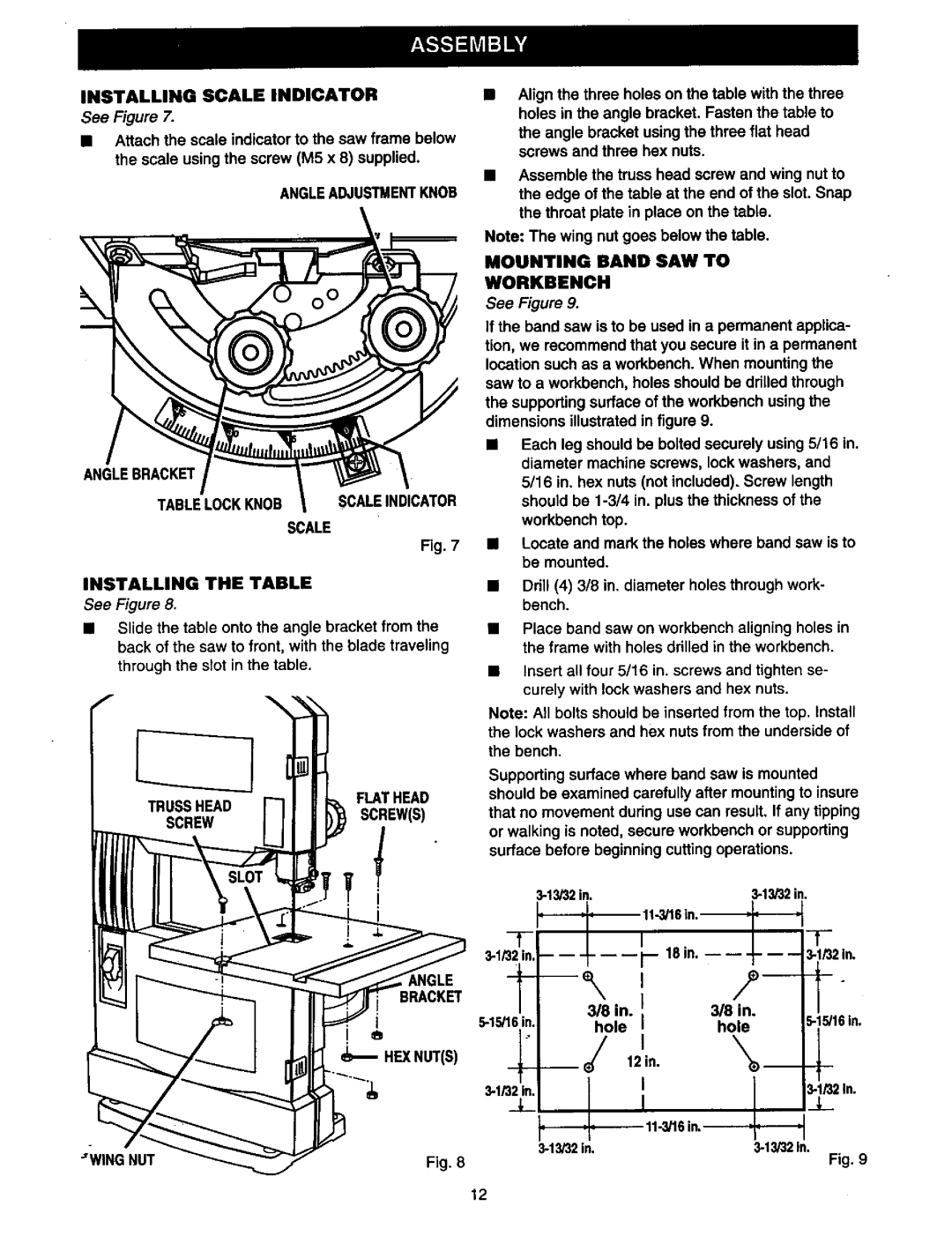
INSTALLING THE TABLE
See Figure 8.
•Slide the table onto the angle bracket from the back of the saw to front, with the blade traveling through the slot in the table.
Align the three holes on the table with the three holes in the angle bracket. Fasten the table to
the angle bracket using the three flat head screws and three hex nuts.
•Assemble the truss head screw and wing nut to the edge of the table at the end of the slot. Snap the throat plate in place on the table.
Note: The wing nut goes below the table.
MOUNTING BAND SAW TO
WORKBENCH
See Figure 9.
If the band saw is to be used in a permanent applica- tion, we recommend that you secure it in a permanent location such as a workbench. When mounting the saw to a workbench, holes should be ddlled through the supporting surface of the workbench using the dimensions illustrated in figure 9.
•Each leg should be bolted securely using 5/16 in. diameter machine screws, lock washers, and 5/16 in. hex nuts (not included). Screw length should be
•Locate and mark the holes where band saw is to be mounted.
•Drill (4) 3/8 in. diameter holes through work- bench.
•Place band saw on workbench aligning holes in the frame with holes drilled in the workbench.
•Insert all four 5/16 in. screws and tighten se- curely with lock washers and hex nuts.
TRUSSHEAD
FLAT HEAD
Note: All bolts should be inserted from the top. Install the lock washers and hex nuts from the underside of the bench.
Supporting surface where band saw is mounted should be examined carefully after mounting to insure
SCREWSCREW(S)
_NGLE
BRACKET
e
HEX NUT(S)
Fig. 8
that no movement during use can result, If any tipping or walking is noted, secure workbench or supporting surface before beginning cutting operations.
|
| I |
| 318 in. I | |
hole | I | |
| /, | 12 in. |
|
| |
_L |
|
|
| ||
Fig. 9
12