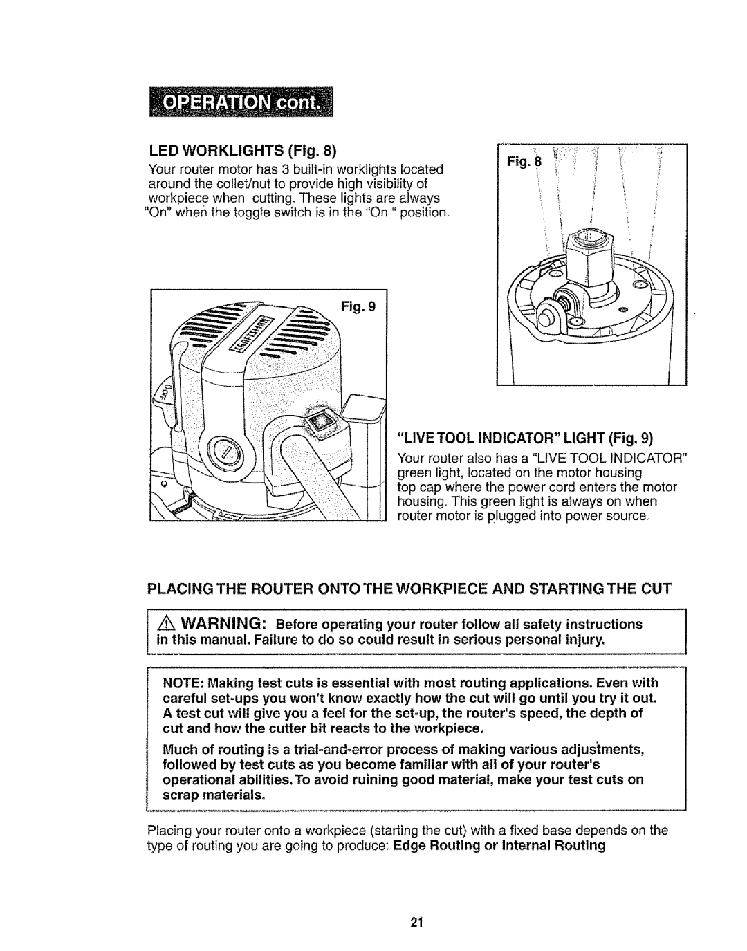
LED WORKLIGHTS (Fig. 8)
Your router motor has 3
Fig. 9
Fig • 8 | " |
i | t |
| + |
"LIVE TOOL INDICATOR" LIGHT (Fig. 9)
Your router also has a "LIVE TOOL INDICATOR" green light, located on the motor housing
top cap where the power cord enters the motor housing, This green light is always on when router motor is plugged into power source.
PLACING THE ROUTER ONTO THE WORKPIECE AND STARTING THE CUT
A WARNING: Before operating your router follow all safety | instructions | I |
in this manual. Failure to do so could result in serious personal | injury. | I |
|
NOTE: Making test cuts is essential with most routing applications. Even with careful
Much of routing is a
Placing your router onto a workpiece (starting the cut) with a fixed base depends on the type of routing you are going to produce: Edge Routing or Internal Routing
21