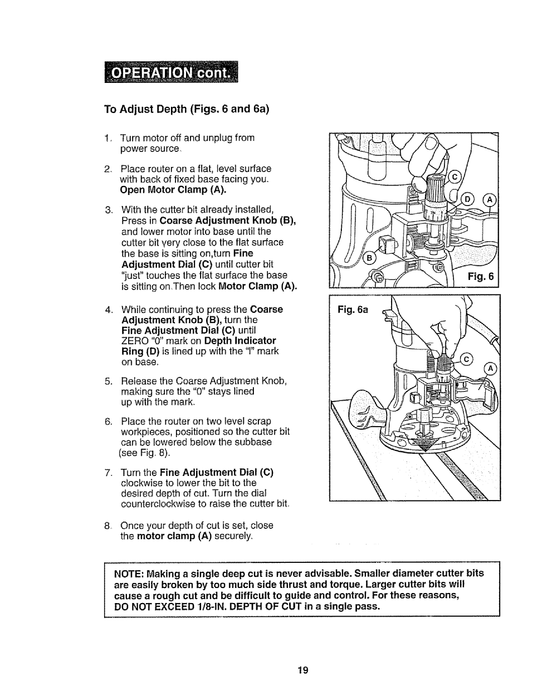
To Adjust Depth (Figs. 6 and 6a)
Turn motor off and unplug from power source°
2_ Place router on a flat, level surface with back of fixed base facing you° Open Motor Clamp (A).
3_
4_
.
.
With the | cutter bit already installed, |
| |||||||
Press | in | Coarse | Adjustment | Knob (B), |
| ||||
and lower motor into base until the |
| ||||||||
cutter bit very close to the flat surface |
| ||||||||
the base is sitting on,turn Fine |
|
|
| ||||||
Adjustment | Dial | (C) | until | cutter | bit |
| |||
"just" | touches | the | flat | surface | the | base | Fig. 6 | ||
is sitting on,Then lock Motor Clamp (A). |
| ||||||||
While | continuing | to press | the | Coarse | Fig. 6a | ||||
Adjustment | Knob (B), turn the |
|
| ||||||
Fine | Adjustment | Dia! | (C) | until |
|
| |||
ZERO "0" mark on Depth Indicator |
| ||||||||
Ring (D) is lined up with the "l" mark on base.
Release the Coarse Adjustment Knob, making sure the "0" stays lined
up with the mark.
Place the router on two level scrap
workpieces, positioned so the cutter bit can be lowered below the subbase
(see Fig. 8).
74Turn the Fine Adjustment Dial (C) clockwise to lower the bit to the
desired depth of cut. Turn the diat
counterclockwise to raise the cutter bit.
8_ Once your depth of cut is set, close the motor clamp (A) securely
NOTE: Making a single deep cut is never advisable. Smaller diameter cutter bits are easily broken by too much side thrust and torque. Larger cutter bits will cause a rough cut and be difficult to guide and control. For these reasons,
DO NOT EXCEED 1/8-1N. DEPTH OF CUT in a single pass.
19
