NOTE:Twomountingbracketsarein- cludedwiththisattachmentBothbrack.- etsareprovidedtoadaptthisattach- mentforusewithpowerheadsthathave eithera1" (2.5cm)diameterora7/8" (2.2cm)diameteruppershaftThecor.- rectbracketmustbeusedtoensurethat thehandlebarismountedsecurelyto theuppershaftbeforeuse.
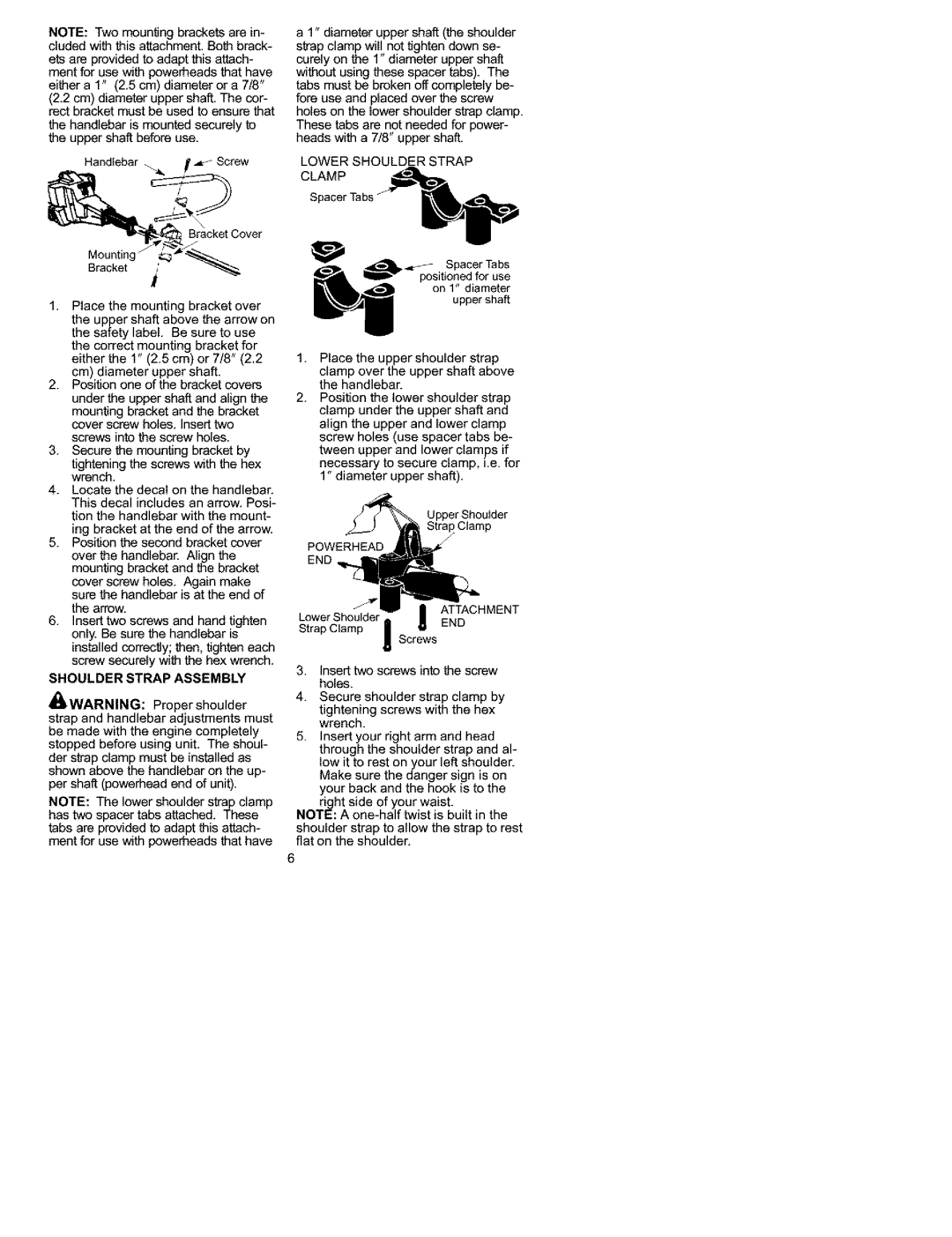
Handlebar __ Screw
_ | Bracket Cover |
Mounting | _.._"_... |
Bracket | i_' |
1.Place the mounting bracket over the upper shaft above the arrow on the safety label. Be sure to use the correct mounting bracket for either the 1" (2.5 cm) or 7/8" (2.2 cm) diameter upper shaft.
2.Position one of the bracket covers
under the upper shaft and align the
mounting bracket and the bracket cover screw holes. Insert two
screws into the screw holes.
3.Secure the mounting bracket by
tightening the screws with the hex wrench.
4.Locate the decal on the handleban This decal includes an arrow. Posi-
a 1" diameter upper shaft (the shoulder strap clamp will not tighten down se- corely on the 1" diameter upper shaft without using these spacer tabs). The tabs must be broken off completely be- fore use and placed over the screw holes on the lower shoulder strap clamp. These tabs are not needed for power- heads with a 7/8" upper shaft.
LOWER SHOULDER STRAP
CLAMP
Spacer Tabs |
|
_ | Spacer Tabs |
positioned for use | |
| upper shaft |
| on 1" diameter |
1.Place the upper shoulder strap
clamp over the upper shaft above the handlebaE
2.Position the lower shoulder strap clamp under the upper shaft and align the upper and lower clamp screw holes (use spacer tabs be- tween upper and lower clamps if necessary to secure clamp, i.e. for 1" diameter upper shaft).
tion the handlebar with the mount- ing bracket at the end of the arrow.
5.Position the second bracket cover over the handlebar. Align the mounting bracket and the bracket cover screw holes. Again make sure the handlebar is at the end of the arrow.
6.Insert two screws and hand tighten only, Be sure the handlebar is installed correctly; then, tighten each screw securely with the hex wrench,
SHOULDER STRAP ASSEMBLY
_WARNING:Proper shoulder
strap and handlebar adjustments must be made with the engine completely stopped before using unit. The shoul- der strap clamp must be installed as shown above the handlebar on the up- per shaft (powerhead end of unit).
NOTE: The lower shoulder strap clamp has two spacer tabs attached. These tabs are provided to adapt this attach- ment for use with powerheeds that have
Strap Clamp /-
POWERHEAD END
|
| ATTACHMENT |
Lower Shoulder | I | END |
Strap Clamp | _crews | |
|
|
3.Insert two screws into the screw holes.
4.Secure shoulder strap clamp by
tightening screws with the hex wrench.
5.Insert your right arm and head through the shoulder strap and al- low it to rest on your left shoulder. Make sure the danger sign is on your back and the hook is to the
right side of your waist.
NOTE: A
shoulder strap to allow the strap to rest flat on the shoulder.
6