changeinskincolorortexture,orloss
offeelingthefingers,hands,or
joints,discontinuetheuseofthistool andseekmedicalattentionAnanti.- vibrationsystemdoesnotguarantee theavoidanceoftheseproblems.
CARTON CONTENTS
Check carton contents against the fol-
lowing list.
Model 358.792442
•Brushcutter attachment
•Handlebar
•Handlebar mounting bracket for 1" (2.5 cm) shaft
•Handlebar mounting bracket for 7/8" (2.2 cm) shaft
•Bracket cover (2)
•Shoulder strap
•Upper shoulder strap clamp
•Lower shoulder strap clamp (with spacer tabs)
•Handlebar bracket screws (4)
•Shoulder strap clamp screws (2)
•
•Large nut for installing blade
•Retaining washer
•Cupped washer
•Metal shield (assembled on brush- cutter attachment)
•Trimmer head
•Plastic shield
•Wing nut (screwed onto plastic shield)
•Attachment Hanger
•Hex Wrench
•Container of line
Examine parts for damage. Do not use damaged parts.
NOTE: If you need assistance or find that parts are missing or damaged, call
ASSEMBLY
zt | _ |
4I_WARNING: | If received assembled, |
repeat all steps to ensure your unit is
properly assembled and all fasteners are secure.
•A hex wrench (provided) is required for assembly.
INSTALLING BRUSHCUTTER AT-
TACHMENT
CAUTION: When removing or instal- ling attachments, place the unit on a flat surface for stability.
Userswhooperatepowertoolsona continualandregularbasismustmoni- torcloselytheirphysicalconditionand theconditionofthistool.
SAVE THESE INSTRUCTIONS
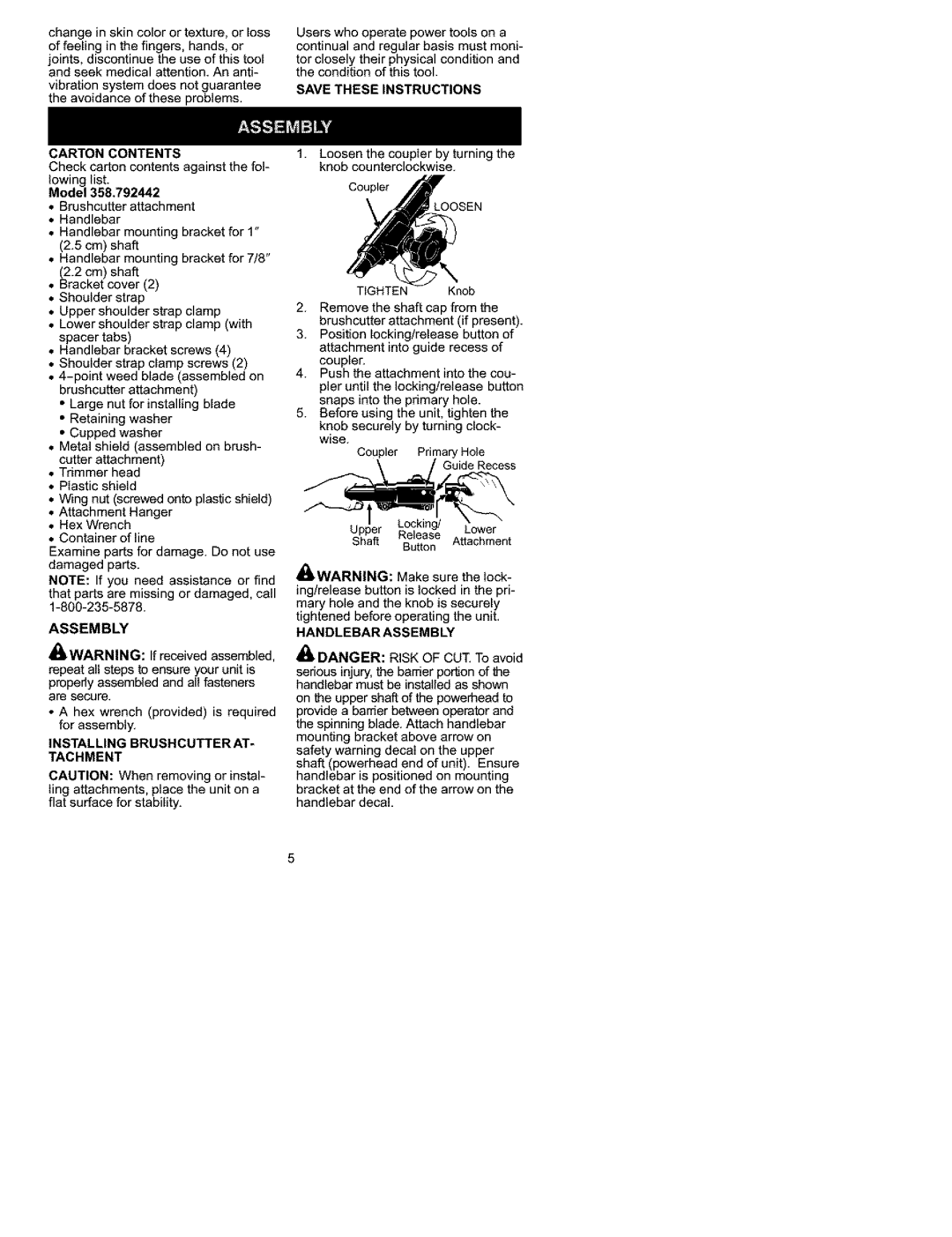
1.Loosen the coupler by turning the knob counterclockwise.
Coupler
LOOSEN
TIGHTEN Knob
2.Remove the shaft cap from the brushcutter attachment (if present).
3.Position locking/release button of attachment into guide recess of coupler.
4.Push the attachment into the cou- pler until the locking/release button snaps into the primary hole.
5.Before using the unit, tighten the
knob securely by turning clock- wise.
Coupler Primary Hole
\ /_uide Recess
UPPa_r Release ALa°c_emr nt
S ft Button t c e
£A | _ |
aWARNING: | Make sure the lock- |
ing/release button is locked in the pri- mary hole and the knob is securely tightened before operating the unit.
HANDLEBAR ASSEMBLY
DANGER: RISK OF CUT. To avoid
serious injury, the barrier portion of the handlebar must be installed as shown
on the upper shaft of the powerheed to provide a barrier between operator and the spinning blade. Attach handlebar mounting bracket above arrow on safety warning decal on the upper shaft powerhead end of unit). Ensure hand ebar s post oned on mount ng bracket at the end of the arrow on the handlebar decal.