ADJUSTMENTSf
Cutting Height
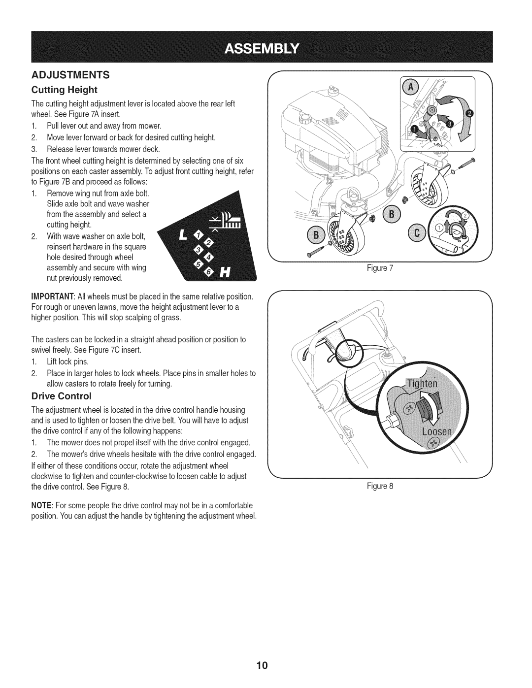
Thecuttingheightadjustmentleverislocatedabovethe rearleft wheel.SeeFigure7Ainsert.
1.Pullleveroutandawayfrommower.
2.Moveleverforwardor backfor desiredcuttingheight.
3.Releaselevertowardsmowerdeck.
Thefrontwheelcuttingheightisdeterminedby selectingoneof six positionsoneachcasterassembly.To adjustfrontcuttingheight,refer to Figure7Bandproceedas follows:
1.Removewing nut fromaxle bolt. Slideaxle bolt andwavewasher fromthe assemblyandselecta cuttingheight.
2.Withwavewasheron axle bolt, reinserthardwarein the square holedesiredthroughwheel assemblyandsecurewithwing nut previouslyremoved.
IMPORTANT:Allwheelsmustbeplacedinthe samerelativeposition. For roughor unevenlawns,movethe heightadjustmentleverto a higherposition.Thiswill stopscalpingof grass.
Thecasterscan belockedina straightaheadpositionor positionto swivelfreely.SeeFigure70 insert.
1.Liftlock pins.
2.Placeinlargerholesto lockwheels.Placepins insmallerholesto allowcastersto rotatefreelyfor turning.
Drive Control
Theadjustmentwheelis locatedin the drivecontrolhandlehousing andis usedto tightenor loosenthe drivebelt.Youwill haveto adjust thedrive controlif any of the followinghappens:
1.The mowerdoes notpropelitself withthedrive controlengaged.
2.The mower'sdrivewheelshesitatewiththe drivecontrolengaged.
Ifeither of theseconditionsoccur,rotatetheadjustmentwheel |
|
clockwiseto |
|
thedrive control.SeeFigure8. | Figure8 |
NOTE:Forsomepeoplethe drivecontrolmaynot beina comfortable |
|
position.Youcan adjustthe handleby tighteningthe adjustmentwheel. |
|
10