NFTZMON
Model Number 917.256544 Ownersmanual
I1. Slope Operation
Safe Operation Practices for Ride-On Mowers
III. Children
Maintenance Agreement
Limited TWO Year Warranty on Craftsman Riding EQUJPIVlENT
Mited 90 DAY Warranty on Battery
Product SPECIFmCATIONS
Index
Engine Maintenance
Perforance
Contents of HARDWARE. Pack
Tools Required for Assembly
HOW to SET UP Your Tractor
T3,-/I 3rLockWAS.ER
To Remove Tractor from Carton
Asse LY
Check Tire Pressure
Check Brake System
Deck See Fig
OSCNARGiNG
Nstall Mulcher PLf4TE See Figs
To Convert to B,GNG or
Lock
Clutch Engaged Clutch Disengaged Hydrostatic Free Wheel
Know Your Tractor
HOW to USE Your Tractor
To SET Parking Brake See Fig
To USE Throttle Control See Fig
Stopping See Fig
0ON
Before Starting the Engine
To Transport
ADD Gasoune
To Start Engine See Fig
Mulching tVIOWiNG TiPS
Service Dates
General Recommendations
Maihtenance Schedule
Before Each USE
To Sharpen Blade See Fig
Custoilities
Tires
Engine
Belts
Transaxle Cooung
Lubrication
Clean AiR Screen See Fig
Clean AiR INTAKE/COOLING Areas
AIR Filter See Fig
Muffler
NoLNE Fuel Rlter See Fg
Cleaning
Engine OL Filter See Fig
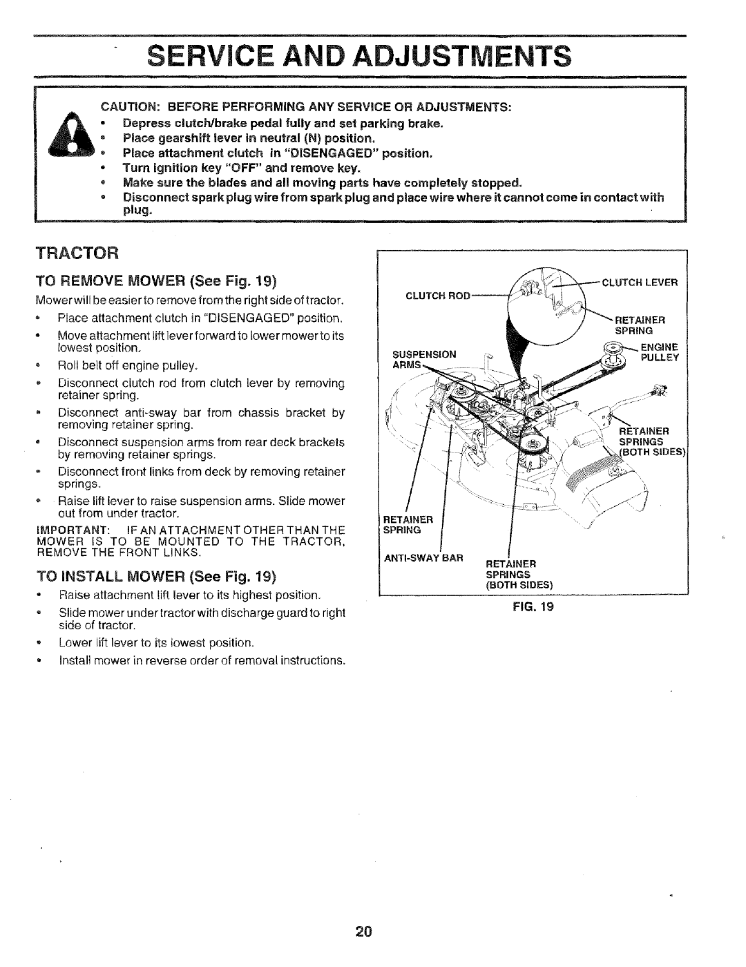
To Remove Mower See Fig
Service Adjustme
To iNSTALL Mower See Fig
Service AI Adjustments
To Level Mower Housing
To Adjust Brake See Fig
See Fig
To Replace Motion Drive Belt
See Fig
To Adjust Teerng Wheel Algnent
TI4ANSAXLE SHIFEI*I Linkage ANE ADo JUSbIENT See qgs
Fbont Wheel TOE4NICAIBER
To Reove Wheel for Epairs
Service Adjustments
To Remove Hood and Grill Assembly See Fig
Positweterminal Negatdveterminal
To Replace Headlight Bulb
DAMAC,E 1O the Heedles
X, 1I,CARBURETOR MW Result if Needle
Tractor
Engne
Fuel System
Engine OIL
OAUSECORRectaM
Problem
TROUBLESHOOT! Points
Cause
Correction
Schematic
GOi
Electrical
KEY
Part
Description
392G
Chassis and Enclosures
KEY Part
Page
Tractor o Model Number 917,256544
Drive
NO. no
Part Descripon
Siesrn G ASSertiVeLY
Description
Steering Assembly
KEY Paft
FL&O @R !OEEL NU , BBR 9!7o25 s544
Seat Assesbly
KEY Part
KEY Part Desgrptio
Tractor o Model Number
Decals
Wheels & Tires
KSY Part
Optional Equipment
Tractor o o Model Number
ENGmNE
Engine
KEY Part Description
Tractor Model Nuiber 917o256544
AOWER Lift 49i
Tractor - Model Number
Mower Lift
KEY
Part Description
Mower Deck
Descrbption
Mower Deck
Descrption
Tractor Model Number
Peerless Transaxle = Model Number 930-057A
Part NO. no Description
Tractor = Model Number 917o256544
REF Part
Kohler Engine o Model Number CV15S Type Nubiber PS-41526
BL..WER Hous Anksnaft
Baffles
Kohler Engine Model Number CV15S, Type Number PS-41526
Crankshaft KEY Part Engine Controls
Tractor = Model Number
Kohler Engine o Model Number CV15S, Type Number PS-4!526
Kohler Engine = Model Number CV15S, Type Number PS-41526
FU EL System
Cymnder HEAD, Valve Breather
KEY Part Descrwption
Kohler Engine Model Number CV15$, Type Number PS41525
Kohler Engine Model Number CV15S, Type Number PS-41526
KEY Part DESCRIPT!ON
OIL PAN / Lubrication Crankcase
KEY Part NO. no
CE Notes
Suggested Guide for SiGHTiNG Slopes for Safe Operation
Part Number Part Description
For Repair SERVICE, Call This Toll Free Number
FON-PART