CTs
3 Setup
3.4Choose Input Wire and Connectors
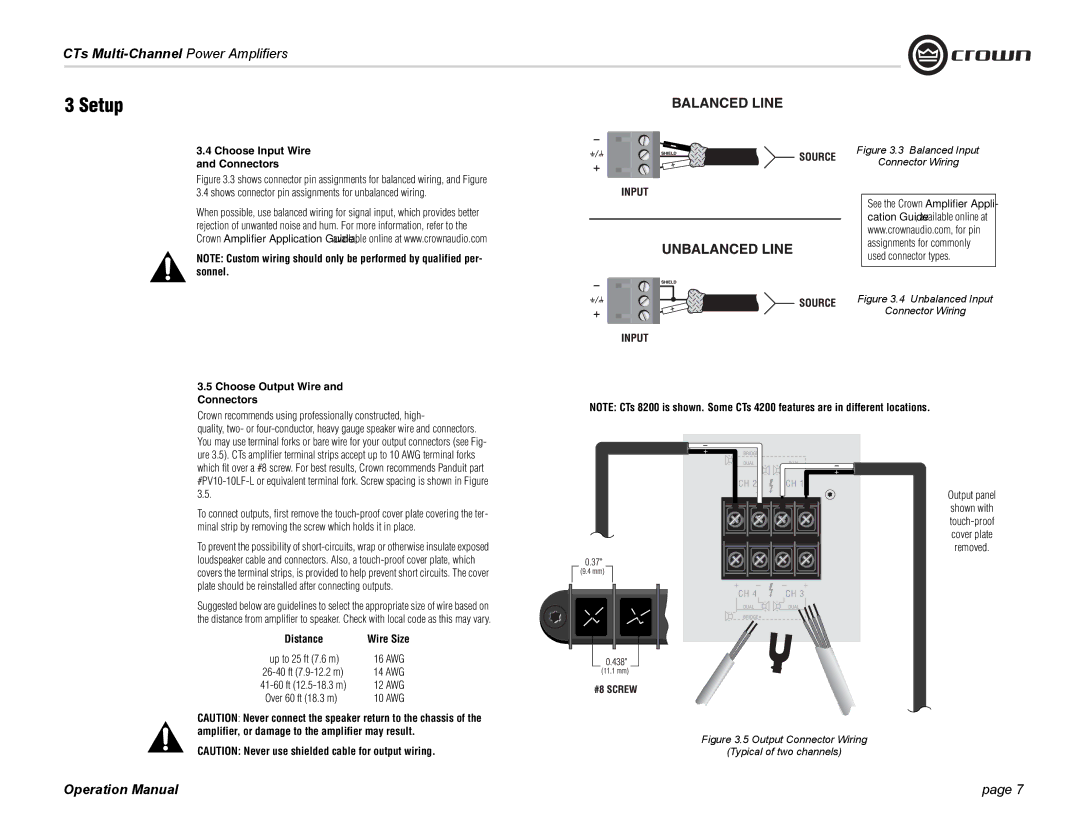
Figure 3.3 shows connector pin assignments for balanced wiring, and Figure 3.4 shows connector pin assignments for unbalanced wiring.
When possible, use balanced wiring for signal input, which provides better rejection of unwanted noise and hum. For more information, refer to the Crown Amplifier Application Guide, available online at www.crownaudio.com
NOTE: Custom wiring should only be performed by qualified per- sonnel.
3.5Choose Output Wire and Connectors
Crown recommends using professionally constructed, high-
quality, two- or
To connect outputs, first remove the
To prevent the possibility of
Suggested below are guidelines to select the appropriate size of wire based on the distance from amplifier to speaker. Check with local code as this may vary.
Distance | Wire Size |
up to 25 ft (7.6 m) | 16 AWG |
14 AWG | |
12 AWG | |
Over 60 ft (18.3 m) | 10 AWG |
CAUTION: Never connect the speaker return to the chassis of the amplifier, or damage to the amplifier may result.
CAUTION: Never use shielded cable for output wiring.
Operation Manual
Figure 3.3 Balanced Input
Connector Wiring
See the Crown Amplifier Appli- cation Guide, available online at www.crownaudio.com, for pin assignments for commonly used connector types.
Figure 3.4 Unbalanced Input
Connector Wiring
NOTE: CTs 8200 is shown. Some CTs 4200 features are in different locations.
Output panel
shown with
Figure 3.5 Output Connector Wiring
(Typical of two channels)
page 7