I-Tech Series Power Amplifiers

4 Advanced Operation

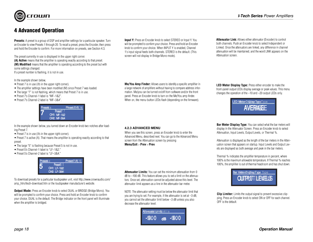
Presets: A preset is a group of DSP and amplifier settings for a particular speaker. Turn an Encoder to view Presets 1 through 20. To recall a preset, press the Encoder, then press and hold the Encoder to confirm. For more information on presets, see Section 4.3.

The preset currently in use is displayed in the upper right corner.

(A)Active means that the amplifier is operating exactly according to that preset.

(M)Modified means that the amplifier is operating according to the preset but with some settings changed.

If a preset number is flashing, it is not in use.

In the example shown below,

Preset 7 is in use (it’s in the upper right corner).

The amplifier settings have been modified (M) since Preset 7 was loaded.

The large “7” is not flashing, which means that Preset 7 is in use.

Preset 7’s Channel-1 label is “MF–1&2”.

Preset 7’s Channel-2 label is “MF–3&4”.

Presets

Preset 7(M)

7

Preset 7


CH1: MF-1&2


CH2: MF-3&4

In the example shown below, you turned down an Encoder knob two notches after load- ing Preset 7.

Preset 7 is in use (it’s in the upper right corner).

Preset 7 is active (A). That means the amplifier is operating exactly according to that preset.

The large “5” is flashing because Preset 5 is not in use.

Preset 5’s Channel-1 label is “LF–1&2.”

Preset 5’s Channel-2 label is “LF–3&4.”

Presets

Preset 7(A)

5

Preset 5


CH1: LF-1&2


CH2: LF-3&4

To download presets for a particular loudspeaker unit, visit http://www.crownaudio.com/ amp_htm/itech-download.htm or the loudspeaker manufacturer’s website.

Output Mode: Press an Encoder knob to select DUAL or BRIDGE (Bridge Mono). You will be prompted to confirm your choice. Press and hold an Encoder knob to confirm your choice. DUAL is the default. The Bridge indicator on the front panel will illuminate when the amplifier is bridged.

Input Y: Press an Encoder knob to select STEREO or Input Y. You will be prompted to confirm your choice. Press and hold an Encoder knob to confirm your choice. When INPUT Y is enabled, Channel 1's input signal feeds both channels. STEREO is the default. (This screen will not display in Bridge Mono mode).

Me/You Amp Finder: Allows users to identify a specific amplifier in a large network of amplifiers without having to compare address infor- mation. Me/you can be turned on/off from software and/or the front panel. Press an Encoder knob to turn on the Me/You amp finder. When on, the menu-button LEDs flash (depending on the firmware).

4.2.3 ADVANCED MENU

When you see this screen, press an Encoder knob to enter the Advanced Menu, described next. You can go to the Advanced Menu screen from the Attenuation screen by pressing

Menu/Exit > Prev > Prev.

Attenuator Limits: You can set the minimum attenuation from 0 dB to –100 dB. This feature allows you to set a limit on the attenua- tors. Once set, attenuation cannot be adjusted above this level. The attenuator limit appears as a line in the attenuator bar meter.

NOTE: The attenuator setting must be below the attenuator limit that you are trying to set. For example, if the attenuator is set at –3 dB, you cannot set the attenuator limit below –3 dB unless you also decrease the attenuator level.

Attenuator Limits

-9.0 -9.0

Attenuator Link: Allows either attenuator (Encoder) to control both channels. Push an Encoder knob to select Independent or Linked. Once the attenuators are linked, any difference in channel attenuation will be maintained, and the word LINK appears on the Attenuation screen.

LED Meter Display Type: Press either encoder to make the front-panel output LEDs display average or peak values. This menu changes the operation of the –10 and –20 output LEDs only.

LED Meter Display Type

AVERAGE

Bar Meter Display Type: You can select what the bar meters will display in the Attenuator Screen. Press an Encoder knob to select Attenuation, Input Levels, Output Levels, or Thermal %.

Attenuation is displayed as the length of the bar meters in the Atten- uation screen that appears on startup. Input Levels and Output Lev- els are displayed as both average and peak in the bar meters.

Thermal % indicates the amplifier temperature in percent, where 100% is the maximum allowable temperature. If Thermal % reaches 100%, the amplifier is out of thermal headroom and has shut down.

Bar Meter Display Type

OUTPUT LEVELS

Clip Limiter: Limits the output signal to prevent excessive clip- ping. Press an Encoder knob to select ON or OFF for each channel. OFF is the default.

page 18

Operation Manual

Page 18
Image 18
Crown Audio I-Tech Series operation manual Menu/Exit Prev Prev, CH1 LF-1&2 CH2 LF-3&4

I-Tech Series specifications

The Crown Audio I-Tech Series represents a pinnacle of power amplification technology, designed to meet the demanding needs of live sound reinforcement and installation applications. Renowned for their flexibility, efficiency, and sound quality, these amplifiers integrate cutting-edge features that appeal to both professional audio engineers and musicians alike.

One of the key technologies employed in the I-Tech Series is the use of DriveCore technology. This innovative design allows the amplifiers to achieve high power output while minimizing size and weight. The DriveCore technology combines the efficiency of Class D amplification with superior sound quality, yielding a lightweight solution that maintains high fidelity and low distortion even at peak volumes.

The I-Tech Series amplifiers come equipped with a comprehensive suite of digital signal processing (DSP) capabilities. Each amplifier integrates sophisticated DSP algorithms that enable advanced speaker management, including extensive equalization, delay settings, and limiting controls. This ensures optimal performance for a variety of loudspeakers and installation scenarios, allowing users to tailor the output to the specific acoustical environment.

Connectivity is another strong point for the I-Tech Series. The amplifiers often include a variety of input options, providing flexibility for different setups, whether analog or digital. The inclusion of Ethercon connectivity enables seamless integration into a networked environment, allowing for remote control and monitoring via Crown's sophisticated software interface. Users can access real-time data about the system's performance, making adjustments on-the-fly to maintain optimal sound quality.

Durability and reliability are fundamental characteristics of the Crown I-Tech amplifiers. Built to withstand the rigors of touring and the demands of permanent installations, these amplifiers are housed in rugged enclosures that dissipate heat effectively while maintaining a compact form factor. Integrated protection circuits safeguard against over-temperature, over-current, and short-circuits, ensuring longevity even under extreme conditions.

In terms of power output, the I-Tech Series features a range of models, each capable of delivering substantial wattage to drive large sound systems with authority. The efficient cooling design allows for extended use without compromising performance, making them suitable for both large concerts and smaller venues.

In summary, the Crown Audio I-Tech Series amplifiers combine advanced technologies, including DriveCore and flexible DSP, to deliver powerful and high-quality audio performance. Their robust design, comprehensive connectivity options, and tailored control make them a premier choice for audio professionals seeking reliable and effective amplification solutions.