AN6077
Figure 2 shows the GPIF Designer view of the FIFO Read waveform.
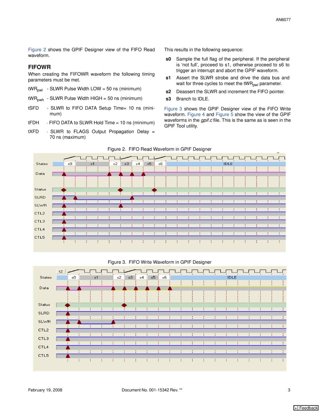
FIFOWR
When creating the FIFOWR waveform the following timing parameters must be met.
tWRpwl - SLWR Pulse Width LOW = 50 ns (minimum)
tWRpwh - SLWR Pulse Width HIGH = 50 ns (minimum)
tSFD - SLWR to FIFO DATA Setup Time= 10 ns (mini- mum)
tFDH - FIFO DATA to SLWR Hold Time = 10 ns (minimum)
This results in the following sequence:
s0 Sample the full flag of the peripheral. If the peripheral is ‘not full’, proceed to s1, otherwise proceed to s6 to trigger an interrupt and abort the GPIF waveform.
s1 Assert the SLWR strobe and drive the data bus and wait for three cycles to meet the tWRpwl parameter.
s2 Deassert the SLWR and increment the FIFO pointer.
s3 Branch to IDLE.
Figure 3 shows the GPIF Designer view of the FIFO Write waveform. Figure 4 and Figure 5 show the view of the GPIF waveforms in the gpif.c file. This is the same as is seen in the GPIF Tool utility.
tXFD - SLWR to FLAGS Output Propagation Delay = 70 ns (maximum)
Figure 2. FIFO Read Waveform in GPIF Designer
Figure 3. FIFO Write Waveform in GPIF Designer
February 19, 2008 | Document No. | 3 |
[+] Feedback