CY62148ESL MoBL®
Pin Configuration
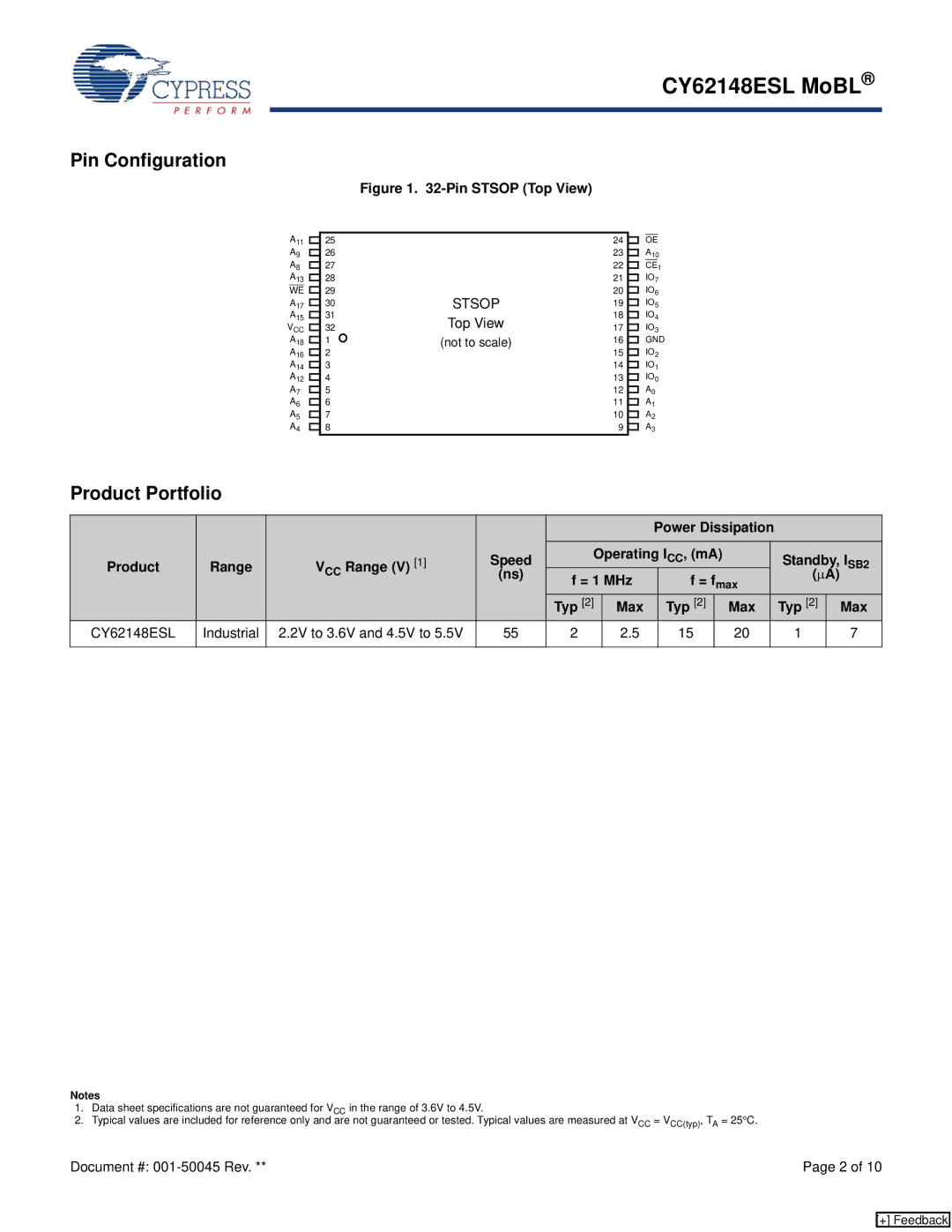
Figure 1. 32-Pin STSOP (Top View)
A11
A9
A8
A13
WE ![]()
A17
A15
VCC
A18
A16
A14
A12
A7
A6
A5
A4
25
26
27
28
29
30
31
32
1
2
3
4
5
6
7
8
| 24 |
|
| OE |
| |
| 23 |
|
| A10 | ||
|
| |||||
| 22 |
|
| CE | 1 | |
|
| |||||
| 21 |
|
| IO7 | ||
|
| |||||
|
| |||||
STSOP | 20 |
|
| IO6 | ||
| ||||||
19 |
|
| IO5 | |||
| ||||||
| ||||||
Top View | 18 |
|
| IO4 | ||
| ||||||
17 |
|
| IO3 | |||
| ||||||
(not to scale) | 16 |
|
| GND | ||
| ||||||
| ||||||
| 15 |
|
| IO2 | ||
|
| |||||
|
| |||||
| 14 |
|
| IO1 | ||
|
| |||||
| 13 |
|
| IO0 | ||
|
| |||||
|
| |||||
| 12 |
|
| A0 | ||
|
| |||||
|
| |||||
| 11 |
|
| A1 | ||
|
| |||||
| 10 |
|
| A2 | ||
|
| |||||
|
| |||||
| 9 |
|
| A3 | ||
|
| |||||
|
| |||||
Product Portfolio
|
|
|
|
|
|
| Power Dissipation |
|
|
|
|
| |||
Product | Range | VCC Range (V) | [1] | Speed | Operating ICC, (mA) |
|
| Standby, I | SB2 | ||||||
| (ns) | f = 1 MHz | f = fmax |
| ( | μ | A) |
| |||||||
|
|
|
|
|
|
|
| ||||||||
|
|
|
|
|
|
|
|
|
|
| |||||
|
|
|
|
| Typ [2] | Max | Typ [2] |
| Max |
| Typ [2] |
| Max | ||
CY62148ESL | Industrial | 2.2V to 3.6V and 4.5V to 5.5V | 55 | 2 | 2.5 | 15 |
| 20 |
| 1 |
|
|
| 7 | |
|
|
|
|
|
|
|
|
|
|
|
|
|
|
|
|
Notes
1.Data sheet specifications are not guaranteed for VCC in the range of 3.6V to 4.5V.
2.Typical values are included for reference only and are not guaranteed or tested. Typical values are measured at VCC = VCC(typ), TA = 25°C.
Document #: | Page 2 of 10 |
[+] Feedback
