CY62148ESL MoBL®
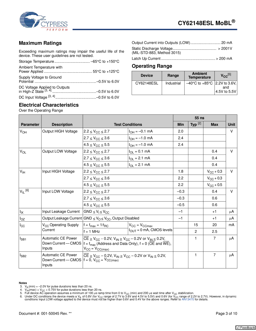
Maximum Ratings
Exceeding maximum ratings may impair the useful life of the device. These user guidelines are not tested.
Storage Temperature | |
Ambient Temperature with |
|
Power Applied | 55°C to +125°C |
Supply Voltage to Ground |
|
Potential | |
DC Voltage Applied to Outputs |
|
in | |
DC Input Voltage [3, 4] |
Output Current into Outputs (LOW) | 20 mA | ||
Static Discharge Voltage |
| > 2001V | |
|
| ||
Latch Up Current |
|
| > 200 mA |
Operating Range |
|
| |
|
|
|
|
Device | Range | Ambient | [5] |
Temperature | VCC | ||
CY62148ESL | Industrial | 2.2V to 3.6V, | |
|
|
| and |
|
|
| 4.5V to 5.5V |
Electrical Characteristics
Over the Operating Range
|
|
|
|
|
|
|
|
|
|
|
|
|
|
|
|
| 55 ns |
|
| |
Parameter | Description |
|
|
|
|
| Test Conditions |
|
|
|
| Min | Typ [2] |
| Max | Unit | ||||
VOH | Output HIGH Voltage | 2.2 | < VCC | < 2.7 |
|
| IOH = |
|
|
| 2.0 |
|
|
| V | |||||
|
| 2.7 | < VCC | < 3.6 |
|
| IOH = |
|
|
| 2.4 |
|
|
|
| |||||
|
| 4.5 | < VCC | < 5.5 |
|
| IOH = |
|
|
| 2.4 |
|
|
|
| |||||
VOL | Output LOW Voltage | 2.2 |
| < VCC | < 2.7 |
|
| IOL = 0.1 mA |
|
|
|
|
|
|
| 0.4 | V | |||
|
| 2.7 | < VCC | < 3.6 |
|
| IOL = 2.1 mA |
|
|
|
|
|
|
| 0.4 |
| ||||
|
| 4.5 | < VCC | < 5.5 |
|
| IOL = 2.1 mA |
|
|
|
|
|
|
| 0.4 |
| ||||
VIH | Input HIGH Voltage | 2.2 |
| < VCC | < 2.7 |
|
|
|
|
|
|
|
| 1.8 |
|
| VCC + 0.3 | V | ||
|
| 2.7 | < VCC | < 3.6 |
|
|
|
|
|
|
|
| 2.2 |
|
| VCC + 0.3 |
| |||
|
| 4.5 | < VCC | < 5.5 |
|
|
|
|
|
|
|
| 2.2 |
|
| VCC + 0.5 |
| |||
VIL [6] | Input LOW Voltage | 2.2 |
| < VCC | < 2.7 |
|
|
|
|
|
|
|
|
|
| 0.4 | V | |||
|
| 2.7 | < VCC | < 3.6 |
|
|
|
|
|
|
|
|
|
| 0.6 |
| ||||
|
| 4.5 | < VCC < 5.5 |
|
|
|
|
|
|
|
|
|
| 0.6 |
| |||||
IIX | Input Leakage Current | GND < VI < VCC |
|
|
|
|
|
|
|
|
|
| +1 | μA | ||||||
IOZ | Output Leakage Current | GND < VO < VCC, Output Disabled |
|
|
|
|
|
| +1 | μA | ||||||||||
ICC | VCC Operating Supply |
| f = fmax = 1/tRC |
|
| VCC = VCCmax |
|
|
|
| 15 |
| 20 | mA | ||||||
| Current |
|
|
|
|
| IOUT = 0 mA, CMOS levels |
|
|
|
|
| ||||||||
|
| f = 1 MHz |
|
|
|
| 2 |
| 2.5 |
| ||||||||||
ISB1 | Automatic CE Power |
|
| > VCC − 0.2V, VIN > VCC – 0.2V or VIN < 0.2V, |
| 1 |
| 7 | μA | |||||||||||
| CE | |||||||||||||||||||
| Down Current — CMOS |
| f = fmax (Address and Data Only), f = 0 (OE and |
|
|
|
|
|
|
| ||||||||||
|
| WE), |
|
|
|
|
| |||||||||||||
| Inputs |
| VCC = VCC(max) |
|
|
|
|
|
|
|
|
|
|
|
|
| ||||
ISB2 | Automatic CE Power |
|
| > V |
| – 0.2V, V | > V |
|
| – 0.2V or V |
| < 0.2V, |
| 1 |
| 7 | μA | |||
| CE | CC | CC | IN | ||||||||||||||||
| Down Current — CMOS |
| f = 0, V | IN |
|
|
|
|
|
|
|
|
|
| ||||||
|
| CC | = VCC(max) |
|
|
|
|
|
|
|
|
|
|
|
|
| ||||
| Inputs |
|
|
|
|
|
|
|
|
|
|
|
|
|
|
|
|
|
| |
|
|
|
|
|
|
|
|
|
|
|
|
|
|
|
|
|
|
|
| |
|
|
|
|
|
|
|
|
|
|
|
|
|
|
|
|
|
|
|
|
|
Notes
3.VIL(min) =
4.VIH(max) = VCC + 0.75V for pulse durations less than 20 ns.
5.Full device AC operation assumes a minimum of 100 μs ramp time from 0 to VCC (min) and 200 μs wait time after VCC stabilization.
6.Under DC conditions the device meets a VIL of 0.8V (for VCC range of 2.7V to 3.6V and 4.5V to 5.5V) and 0.6V (for VCC range of 2.2V to 2.7V). However, in dynamic conditions Input LOW voltage applied to the device must not be higher than 0.6V and 0.4V for the above ranges. Refer to AN13470 for details.
Document #: | Page 3 of 10 |
[+] Feedback