CY7C1353G
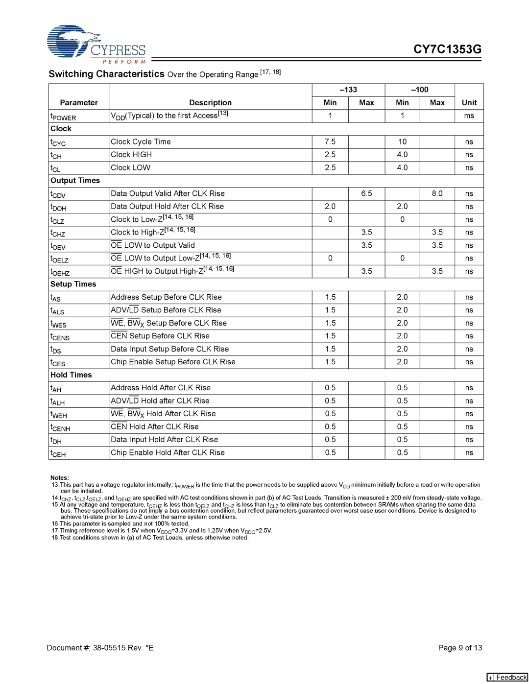
Switching Characteristics Over the Operating Range [17, 18]
|
|
|
|
|
|
|
|
|
|
|
|
| ||||
Parameter |
|
|
|
|
|
|
|
| Description |
|
|
|
|
| Unit | |
|
|
|
|
|
|
|
| Min |
| Max | Min |
| Max | |||
|
|
|
|
|
|
|
|
|
| |||||||
tPOWER |
| VDD(Typical) to the first Access[13] | 1 |
|
| 1 |
|
| ms | |||||||
Clock |
|
|
|
|
|
|
|
|
|
|
|
|
|
|
| |
|
|
|
|
|
|
|
|
| ||||||||
tCYC |
| Clock Cycle Time | 7.5 |
|
| 10 |
|
| ns | |||||||
tCH |
| Clock HIGH | 2.5 |
|
| 4.0 |
|
| ns | |||||||
tCL |
| Clock LOW | 2.5 |
|
| 4.0 |
|
| ns | |||||||
Output Times |
|
|
|
|
|
|
|
|
|
|
|
|
|
|
| |
|
|
|
|
|
|
|
|
| ||||||||
tCDV |
| Data Output Valid After CLK Rise |
|
| 6.5 |
|
| 8.0 | ns | |||||||
tDOH |
| Data Output Hold After CLK Rise | 2.0 |
|
| 2.0 |
|
| ns | |||||||
t |
| Clock to | 0 |
|
| 0 |
|
| ns | |||||||
CLZ |
|
|
|
|
|
|
|
|
|
|
|
|
|
|
|
|
t |
| Clock to |
|
| 3.5 |
|
| 3.5 | ns | |||||||
CHZ |
|
|
|
|
|
|
|
|
|
|
|
|
|
|
|
|
tOEV |
|
|
| LOW to Output Valid |
|
| 3.5 |
|
| 3.5 | ns | |||||
OE |
|
|
| |||||||||||||
tOELZ |
|
|
| LOW to Output | 0 |
|
| 0 |
|
| ns | |||||
OE |
|
|
| |||||||||||||
tOEHZ |
|
|
| HIGH to Output |
|
| 3.5 |
|
| 3.5 | ns | |||||
OE |
|
|
| |||||||||||||
Setup Times |
|
|
|
|
|
|
|
|
|
|
|
|
|
|
| |
|
|
|
|
|
|
|
|
| ||||||||
tAS |
| Address Setup Before CLK Rise | 1.5 |
|
| 2.0 |
|
| ns | |||||||
tALS |
|
|
|
|
|
|
|
|
|
|
|
|
|
|
|
|
ADV/LD |
| Setup Before CLK Rise | 1.5 |
|
| 2.0 |
|
| ns | |||||||
tWES |
|
|
|
|
|
|
|
| X Setup Before CLK Rise | 1.5 |
|
| 2.0 |
|
| ns |
WE, | BW |
|
|
| ||||||||||||
tCENS |
|
|
|
| Setup Before CLK Rise | 1.5 |
|
| 2.0 |
|
| ns | ||||
CEN |
|
|
| |||||||||||||
tDS |
| Data Input Setup Before CLK Rise | 1.5 |
|
| 2.0 |
|
| ns | |||||||
tCES |
| Chip Enable Setup Before CLK Rise | 1.5 |
|
| 2.0 |
|
| ns | |||||||
Hold Times |
|
|
|
|
|
|
|
|
|
|
|
|
|
|
| |
|
|
|
|
|
|
|
|
| ||||||||
tAH |
| Address Hold After CLK Rise | 0.5 |
|
| 0.5 |
|
| ns | |||||||
tALH |
|
|
|
|
|
|
|
|
|
|
|
|
|
|
|
|
ADV/LD | Hold after CLK Rise | 0.5 |
|
| 0.5 |
|
| ns | ||||||||
tWEH |
|
|
|
|
|
|
| X Hold After CLK Rise | 0.5 |
|
| 0.5 |
|
| ns | |
WE, | BW |
|
|
| ||||||||||||
tCENH |
|
|
|
| Hold After CLK Rise | 0.5 |
|
| 0.5 |
|
| ns | ||||
CEN |
|
|
| |||||||||||||
tDH |
| Data Input Hold After CLK Rise | 0.5 |
|
| 0.5 |
|
| ns | |||||||
tCEH |
| Chip Enable Hold After CLK Rise | 0.5 |
|
| 0.5 |
|
| ns | |||||||
Notes:
13.This part has a voltage regulator internally; tPOWER is the time that the power needs to be supplied above VDD minimum initially before a read or write operation can be initiated.
14.tCHZ, tCLZ,tOELZ, and tOEHZ are specified with AC test conditions shown in part (b) of AC Test Loads. Transition is measured ± 200 mV from
achieve
17.Timing reference level is 1.5V when VDDQ=3.3V and is 1.25V when VDDQ=2.5V. 18.Test conditions shown in (a) of AC Test Loads, unless otherwise noted.
Document #: | Page 9 of 13 |
[+] Feedback
