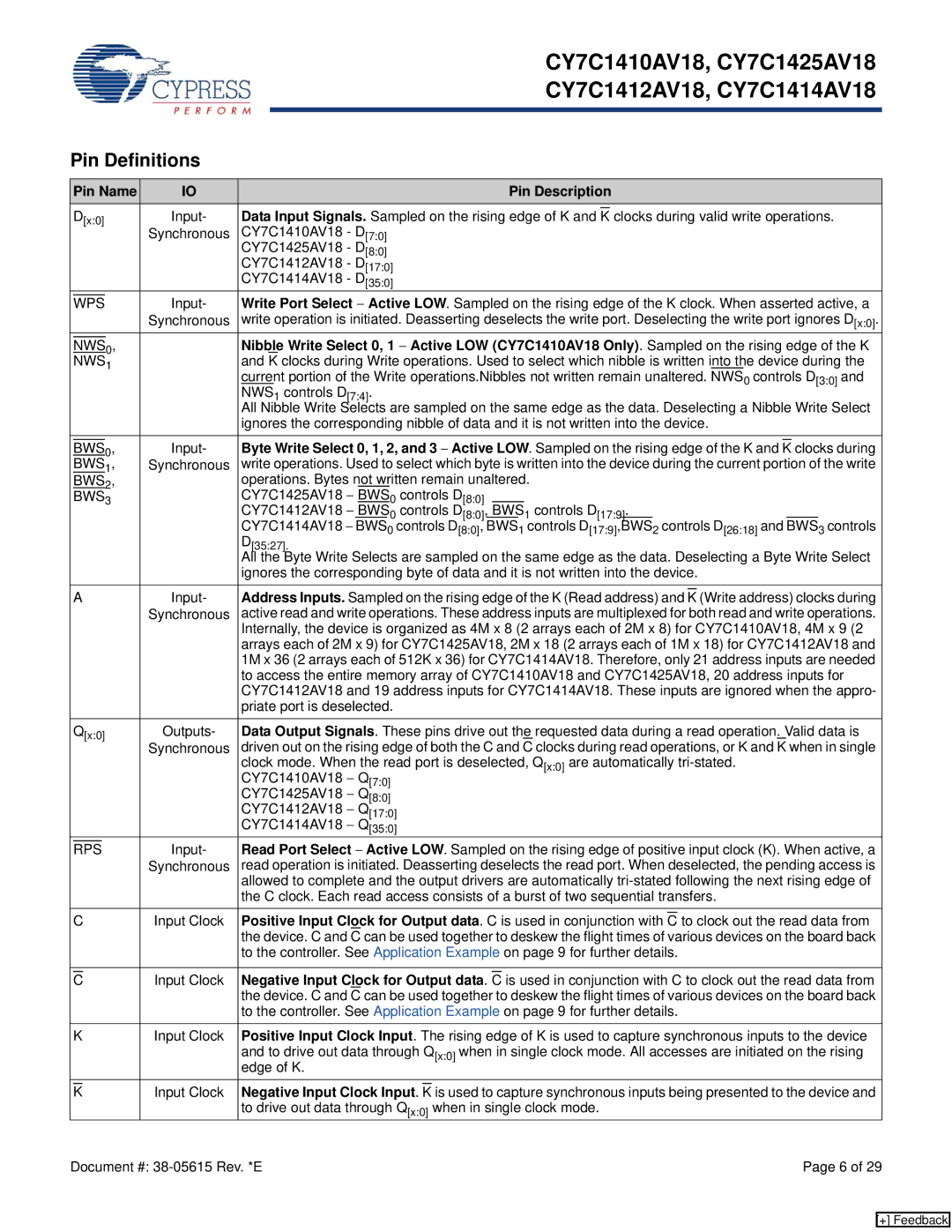
Cypress CY7C1414AV18, CY7C1410AV18, CY7C1425AV18 manual Pin Definitions, Pin Name Pin Description

Models: CY7C1410AV18 CY7C1425AV18 CY7C1414AV18 CY7C1412AV18

1 29
Download 29 pages 29.82 Kb
Page 6
Image 6


CY7C1410AV18, CY7C1425AV18


CY7C1412AV18, CY7C1414AV18


Pin Definitions


Pin Name

IO


Pin Description


D[x:0]

Input-

Data Input Signals. Sampled on the rising edge of K and


clocks during valid write operations.


K


Synchronous

CY7C1410AV18 - D[7:0]


CY7C1425AV18 - D[8:0]


CY7C1412AV18 - D[17:0]


CY7C1414AV18 - D[35:0]


Input-

Write Port Select Active LOW. Sampled on the rising edge of the K clock. When asserted active, a


WPS


Synchronous

write operation is initiated. Deasserting deselects the write port. Deselecting the write port ignores D[x:0].


0,


Nibble Write Select 0, 1 Active LOW (CY7C1410AV18 Only). Sampled on the rising edge of the K


NWS


NWS1


and K clocks during Write operations. Used to select which nibble is written into the device during the


current portion of the Write operations.Nibbles not written remain unaltered. NWS0 controls D[3:0] and


NWS1 controls D[7:4].


All Nibble Write Selects are sampled on the same edge as the data. Deselecting a Nibble Write Select


ignores the corresponding nibble of data and it is not written into the device.


0,

Input-

Byte Write Select 0, 1, 2, and 3 Active LOW. Sampled on the rising edge of the K and


clocks during


BWS

K


BWS1,

Synchronous

write operations. Used to select which byte is written into the device during the current portion of the write


BWS2,


operations. Bytes not written remain unaltered.


BWS3


CY7C1425AV18 BWS0

controls D[8:0]


CY7C1412AV18 BWS0

controls D[8:0],

BWS


1 controls D[17:9]

.


CY7C1414AV18 BWS0 controls D[8:0], BWS1 controls D[17:9],BWS2 controls D[26:18] and BWS3 controls


D[35:27].


All the Byte Write Selects are sampled on the same edge as the data. Deselecting a Byte Write Select


ignores the corresponding byte of data and it is not written into the device.


A

Input-

Address Inputs. Sampled on the rising edge of the K (Read address) and


(Write address) clocks during


K


Synchronous

active read and write operations. These address inputs are multiplexed for both read and write operations.


Internally, the device is organized as 4M x 8 (2 arrays each of 2M x 8) for CY7C1410AV18, 4M x 9 (2


arrays each of 2M x 9) for CY7C1425AV18, 2M x 18 (2 arrays each of 1M x 18) for CY7C1412AV18 and


1M x 36 (2 arrays each of 512K x 36) for CY7C1414AV18. Therefore, only 21 address inputs are needed


to access the entire memory array of CY7C1410AV18 and CY7C1425AV18, 20 address inputs for


CY7C1412AV18 and 19 address inputs for CY7C1414AV18. These inputs are ignored when the appro-


priate port is deselected.


Q[x:0]

Outputs-

Data Output Signals. These pins drive out the requested data during a read operation. Valid data is


Synchronous

driven out on the rising edge of both the C and C clocks during read operations, or K and K when in single


clock mode. When the read port is deselected, Q[x:0] are automatically tri-stated.


CY7C1410AV18 Q[7:0]


CY7C1425AV18 Q[8:0]


CY7C1412AV18 Q[17:0]


CY7C1414AV18 Q[35:0]


Input-

Read Port Select Active LOW. Sampled on the rising edge of positive input clock (K). When active, a


RPS


Synchronous

read operation is initiated. Deasserting deselects the read port. When deselected, the pending access is


allowed to complete and the output drivers are automatically tri-stated following the next rising edge of


the C clock. Each read access consists of a burst of two sequential transfers.


CInput Clock Positive Input Clock for Output data. C is used in conjunction with C to clock out the read data from the device. C and C can be used together to deskew the flight times of various devices on the board back to the controller. See Application Example on page 9 for further details.

CInput Clock Negative Input Clock for Output data. C is used in conjunction with C to clock out the read data from the device. C and C can be used together to deskew the flight times of various devices on the board back to the controller. See Application Example on page 9 for further details.

K

Input Clock Positive Input Clock Input. The rising edge of K is used to capture synchronous inputs to the device


and to drive out data through Q[x:0] when in single clock mode. All accesses are initiated on the rising


edge of K.

KInput Clock Negative Input Clock Input. K is used to capture synchronous inputs being presented to the device and to drive out data through Q[x:0] when in single clock mode.

Document #: 38-05615 Rev. *E

Page 6 of 29

[+] Feedback

Page 6
Image 6
Cypress CY7C1414AV18, CY7C1410AV18, CY7C1425AV18, CY7C1412AV18 manual Pin Definitions, Pin Name Pin Description

CY7C1410AV18, CY7C1425AV18, CY7C1414AV18, CY7C1412AV18 specifications

Cypress Semiconductor, a prominent player in the semiconductor industry, offers a robust lineup of synchronous Static Random Access Memory (SRAM) products, including the CY7C1412AV18, CY7C1414AV18, CY7C1425AV18, and CY7C1410AV18. These memory chips are designed for high-performance applications, showcasing significant advancements in speed, density, and power efficiency.

The CY7C1412AV18 is a 1.2 Megabit SRAM with a 2.5V operating voltage. It boasts a maximum access time of 12 nanoseconds, specifically engineered for applications requiring fast data processing. This chip is particularly well-suited for networking and telecommunications applications where quick data retrieval is essential.

Next in the lineup, the CY7C1414AV18 offers a 1.44 Megabit capacity with a similar operating voltage and access time. This model's increased density allows for more data storage while maintaining performance levels, making it an excellent choice for automotive and industrial applications that demand reliability and speed.

Moreover, the CY7C1425AV18 is a more advanced solution with a 2 Megabit capacity. It integrates innovative features such as pipelined architecture, which enhances throughput and minimizes latency, making it ideal for high-speed processing applications like video and image processing in various electronic devices.

Lastly, the CY7C1410AV18 rounds out the series with a 1 Megabit capacity and is tailored for critical applications where space and power consumption are constraints. Its low power consumption makes it increasingly suitable for battery-operated devices, contributing to energy efficiency and extended operational life.

Each of these memory chips incorporates Cypress's advanced technology, including CMOS (Complementary Metal-Oxide-Semiconductor) fabrication processes, which ensures high performance while maintaining low static and dynamic power consumption. The SRAMs are designed with a 3.3V data interface, ensuring compatibility with modern digital systems.

In summary, Cypress's CY7C1412AV18, CY7C1414AV18, CY7C1425AV18, and CY7C1410AV18 SRAM chips stand out with their high access speeds, low power consumption, and varying capacities. These components are optimized for a wide range of applications, including networking, automotive, and consumer electronics, confirming Cypress's commitment to delivering cutting-edge memory solutions to meet the evolving demands of the electronics industry.