CY7C68003
Operation Modes
There are six operation modes available in TX2UL. They are:
■Normal Operation Mode
■Configuration Mode
■ULPI Low Power Mode
■Sleep Mode
■Carkit UART Pass Through Mode
■
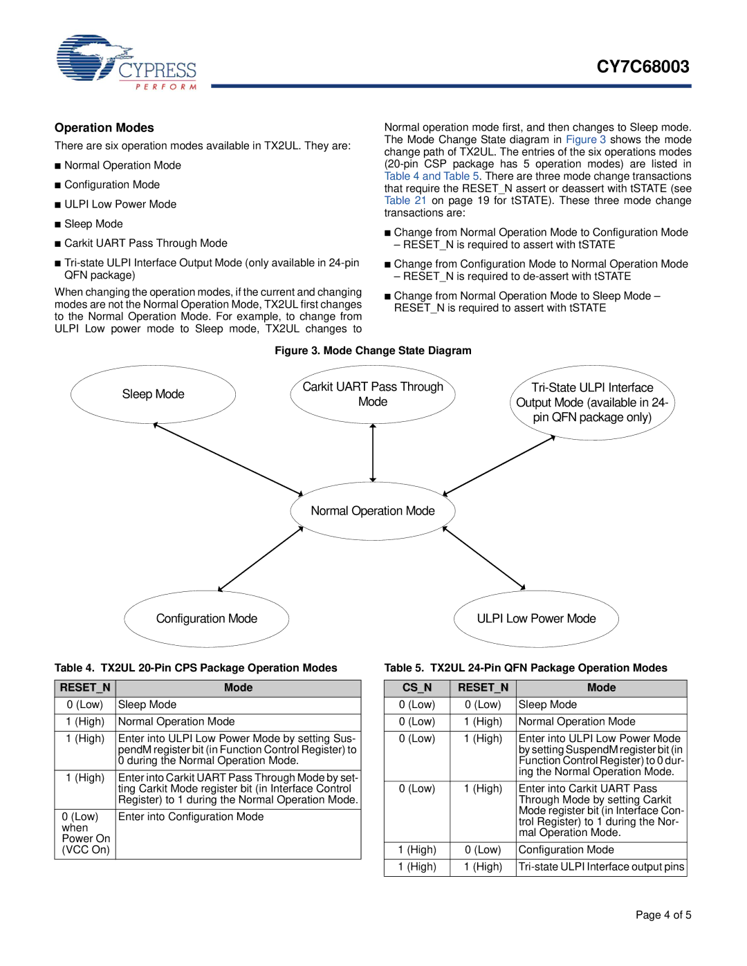
When changing the operation modes, if the current and changing modes are not the Normal Operation Mode, TX2UL first changes to the Normal Operation Mode. For example, to change from ULPI Low power mode to Sleep mode, TX2UL changes to
Normal operation mode first, and then changes to Sleep mode. The Mode Change State diagram in Figure 3 shows the mode change path of TX2UL. The entries of the six operations modes
■Change from Normal Operation Mode to Configuration Mode
–RESET_N is required to assert with tSTATE
■Change from Configuration Mode to Normal Operation Mode
–RESET_N is required to
■Change from Normal Operation Mode to Sleep Mode – RESET_N is required to assert with tSTATE
| Figure 3. Mode Change State Diagram |
| |
Sleep Mode | Carkit UART Pass Through | ||
Mode | Output Mode (available in 24- | ||
| |||
|
| pin QFN package only) |
Normal Operation Mode
Configuration Mode | ULPI Low Power Mode |
Table 4. TX2UL 20-Pin CPS Package Operation Modes
RESET_N | Mode |
0 (Low) | Sleep Mode |
|
|
1 (High) | Normal Operation Mode |
|
|
1 (High) | Enter into ULPI Low Power Mode by setting Sus- |
| pendM register bit (in Function Control Register) to |
| 0 during the Normal Operation Mode. |
1 (High) | Enter into Carkit UART Pass Through Mode by set- |
| ting Carkit Mode register bit (in Interface Control |
| Register) to 1 during the Normal Operation Mode. |
0 (Low) | Enter into Configuration Mode |
when |
|
Power On |
|
(VCC On) |
|
Table 5. TX2UL 24-Pin QFN Package Operation Modes
CS_N | RESET_N | Mode |
0 (Low) | 0 (Low) | Sleep Mode |
|
|
|
0 (Low) | 1 (High) | Normal Operation Mode |
|
|
|
0 (Low) | 1 (High) | Enter into ULPI Low Power Mode |
|
| by setting SuspendM register bit (in |
|
| Function Control Register) to 0 dur- |
|
| ing the Normal Operation Mode. |
0 (Low) | 1 (High) | Enter into Carkit UART Pass |
|
| Through Mode by setting Carkit |
|
| Mode register bit (in Interface Con- |
|
| trol Register) to 1 during the Nor- |
|
| mal Operation Mode. |
1 (High) | 0 (Low) | Configuration Mode |
|
|
|
1 (High) | 1 (High) | |
|
|
|
Page 4 of 5