Section 1 - Product Overview
Hardware Overview
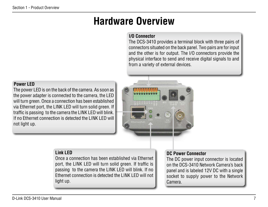
I/O Connector
The
Power LED
The power LED is on the back of the camera. As soon as the power adapter is connected to the camera, the LED will turn green. Once a connection has been established via Ethernet port, the LINK LED will turn solid green. If traffic is passing to the camera the LINK LED will blink. If no Ethernet connection is detected the LINK LED will not light up.
Link LED
Once a connection has been established via Ethernet port, the LINK LED will turn solid green. If traffic is passing to the camera the LINK LED will blink. If no Ethernet connection is detected the LINK LED will not light up.
DC Power Connector
The DC power input connector is located on the