Check SIM Sensor Connections
4.Slide the
5.Press the sensor cable firmly and completely into the
Note: | The pole can pinch or cause wear on the anemometer cable if the cable is not pressed com- |
| pletely into the channel at the bottom of the groove. |
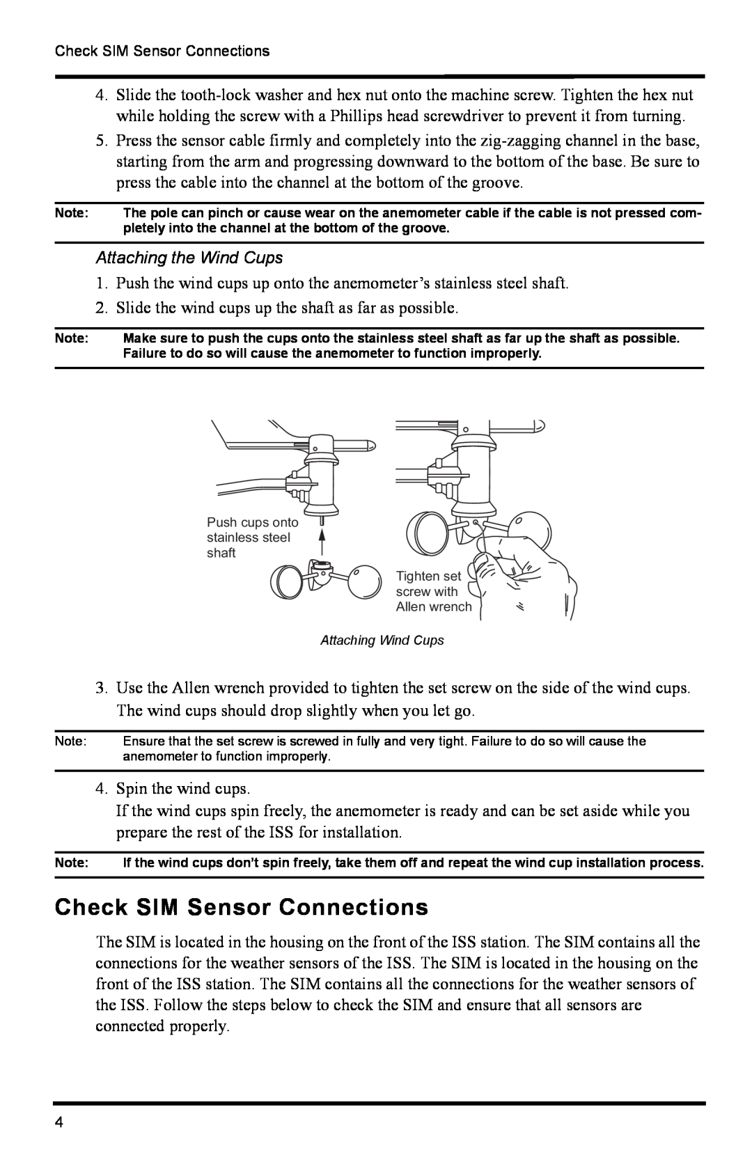
Attaching the Wind Cups
1.Push the wind cups up onto the anemometer’s stainless steel shaft.
2.Slide the wind cups up the shaft as far as possible.
Note: | Make sure to push the cups onto the stainless steel shaft as far up the shaft as possible. | ||||||||||||||||||
| Failure to do so will cause the anemometer to function improperly. | ||||||||||||||||||
|
|
|
|
|
|
|
|
|
|
|
|
|
|
|
|
|
|
|
|
|
|
|
|
|
|
|
|
|
|
|
|
|
|
|
|
|
|
|
|
|
|
|
|
|
|
|
|
|
|
|
|
|
|
|
|
|
|
|
|
|
|
|
|
|
|
|
|
|
|
|
|
|
|
|
|
|
|
|
|
|
|
|
|
|
|
|
|
|
|
|
|
|
|
|
|
|
|
|
|
|
|
|
|
|
|
|
|
|
|
|
|
|
|
|
|
|
|
|
|
|
|
|
|
|
|
|
|
|
|
|
|
|
|
|
|
|
|
|
|
|
|
|
|
|
|
|
|
|
|
|
|
|
|
|
|
|
|
|
|
|
|
|
|
|
|
|
|
|
|
|
|
|
|
|
|
|
|
|
|
|
|
|
|
|
|
|
|
|
|
|
|
|
|
|
|
|
|
|
|
|
|
|
|
|
|
|
|
|
|
|
|
|
|
|
|
|
|
|
|
|
|
|
|
|
|
|
|
|
|
|
|
|
|
|
|
|
|
|
|
Push cups onto stainless steel shaft
Tighten set ![]()
![]()
![]() screw with
screw with ![]()
![]() Allen wrench
Allen wrench ![]()
![]()
Attaching Wind Cups
3.Use the Allen wrench provided to tighten the set screw on the side of the wind cups. The wind cups should drop slightly when you let go.
Note: | Ensure that the set screw is screwed in fully and very tight. Failure to do so will cause the |
| anemometer to function improperly. |
4.Spin the wind cups.
If the wind cups spin freely, the anemometer is ready and can be set aside while you prepare the rest of the ISS for installation.
Note: | If the wind cups don’t spin freely, take them off and repeat the wind cup installation process. |
|
|
Check SIM Sensor Connections
The SIM is located in the housing on the front of the ISS station. The SIM contains all the connections for the weather sensors of the ISS. The SIM is located in the housing on the front of the ISS station. The SIM contains all the connections for the weather sensors of the ISS. Follow the steps below to check the SIM and ensure that all sensors are connected properly.
4