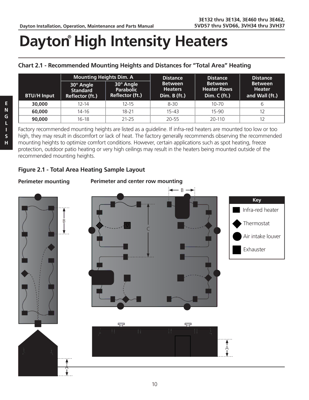
3E460, 3E462, 3.00E+132, 3.00E+134, 5VD57 specifications
Dayton 3.00E+134, 5VD57, 3E462, 3E460, 3.00E+132 is a distinctive model within the Dayton series known for its advanced performance in various applications. This line of products is designed to meet the demands of both commercial and industrial sectors, showcasing a blend of efficiency, durability, and innovative technology.One of the main features of the Dayton 3.00E+134 series is its powerful motor capabilities. The models utilize high-efficiency motors that ensure optimal energy consumption while providing robust operational performance. This not only helps to reduce utility costs but also plays a crucial role in minimizing the environmental footprint.
The technology behind Dayton products often incorporates advanced electronic controls that allow for precise adjustments and operations. This feature is particularly beneficial in environments where maintaining specific conditions is essential, such as HVAC systems and industrial processes. The electronic controls provide users with greater flexibility and range in performance settings, accommodating various operational requirements.
In terms of construction, the Dayton 3.00E+134 models are built with high-quality materials that ensure long-lasting durability. This is critical in settings where equipment is subjected to heavy usage or challenging environmental conditions. The robust design and protective coatings prevent corrosion and wear, ensuring that the equipment maintains its functionality over extended periods.
Another characteristic worth noting is the versatile range of applications for these models. They can be used in air movement, ventilation, heating, and cooling systems, making them highly valued in multiple sectors, such as manufacturing, healthcare, and commercial buildings. Their adaptability means they can seamlessly integrate into existing systems without requiring extensive modifications.
The ease of installation and maintenance is also a highlight of the Dayton 3.00E+134 series. The design facilitates quick assembly and access for servicing, saving valuable time and labor costs. Users appreciate the convenience offered, allowing them to focus on core business operations without prolonged downtime.
Furthermore, these models comply with industry standards and regulations, ensuring safety and reliability in operation. Overall, the Dayton 3.00E+134, 5VD57, 3E462, 3E460, 3.00E+132 series represents a pinnacle in engineering excellence, delivering exceptional performance across various applications while prioritizing energy efficiency and user-friendly functionality.

