Operation User Setup
AFS 224
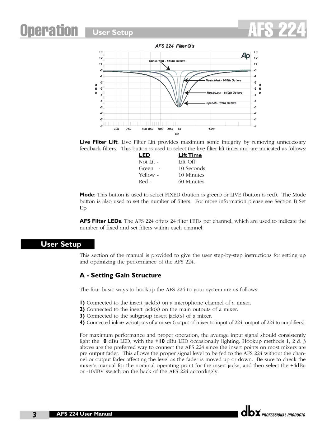
AFS 224 Filter Q's
| +3 |
|
|
|
|
|
| +3 |
|
| +2 |
|
|
|
|
|
| +2 |
|
|
|
| Music High - 1/80th Octave |
|
|
| |||
| +1 |
|
|
|
|
|
| +1 |
|
|
|
|
|
|
|
|
| ||
|
|
|
|
|
|
|
| ||
|
|
|
|
|
| Music Med - 1/20th Octave |
| ||
d |
|
|
|
|
|
| d | ||
|
|
|
|
|
|
|
| ||
B |
|
|
|
|
|
| B | ||
u |
|
|
|
|
| Music Low - 1/10th Octave | u | ||
|
|
|
|
|
| Speech - 1/5th Octave |
| ||
|
|
|
|
|
|
|
|
| |
|
|
|
|
|
|
|
| ||
|
|
|
|
|
|
|
| ||
|
|
|
|
|
|
|
| ||
|
|
|
|
|
|
|
| ||
| 700 | 750 | 820 850 | 900 | .95k | 1k | 1.2k |
|
|
|
|
|
|
|
| Hz |
|
|
|
Live Filter Lift: Live Filter Lift provides maximum sonic integrity by removing unnecessary feedback filters. This button is used to select the live filter lift times and are indicated as follows:
LED | Lift Time | |
Not Lit - | Lift Off | |
Green - | 10 | Seconds |
Yellow - | 10 | Minutes |
Red - | 60 | Minutes |
Mode: This button is used to select FIXED (button is green) or LIVE (button is red). The Mode button is also used to set the number of filters. For more information please see Section B Set Up
AFS Filter LEDs: The AFS 224 offers 24 filter LEDs per channel, which are used to indicate the number of fixed and set filters within each channel.
User Setup
This section of the manual is provided to give the user
A - Setting Gain Structure
The four basic ways to hookup the AFS 224 to your system are as follows:
1)Connected to the insert jack(s) on a microphone channel of a mixer.
2)Connected to the insert jack(s) on the main outputs of a mixer.
3)Connected to the subgroup insert jack(s) of a mixer.
4)Connected inline w/outputs of a mixer (output of mixer to input of 224, output of 224 to amplifiers).
For maximum performance and proper operation, the average input signal should consistently light the 0 dBu LED, with the +10 dBu LED occasionally lighting. Hookup methods 1, 2 & 3 above are the preferred way to connect the AFS 224 since the insert points on most mixers are pre output fader. This allows the proper signal level to be fed to the AFS 224 without the chan- nel or output fader affecting the level as the fader is moved up or down. Be sure to check the mixer’s manual for the nominal operating point for the insert jacks, and then select the +4dBu or
®
3 | AFS 224 User Manual |
|
|
