Operation | Application Guide | AFS 224 | |
|
|
|
|
Applications
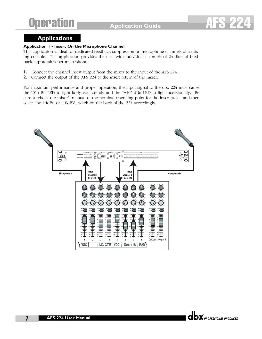
Application 1 - Insert On the Microphone Channel
This application is ideal for dedicated feedback suppression on microphone channels of a mix- ing console. This application provides the user with individual channels of 24 filter of feed- back suppression per microphone.
1.Connect the channel insert output from the mixer to the input of the AFS 224.
2.Connect the output of the AFS 224 to the insert return of the mixer.
For maximum performance and proper operation, the input signal to the dbx 224 must cause the “0” dBu LED to light fairly consistently and the “+10” dBu LED to light occasionally. Be sure to check the mixer’s manual of the nominal operating point for the insert jacks, and then select the +4dBu or
|
|
|
|
|
|
|
|
|
|
|
|
|
|
|
|
|
|
|
|
|
|
|
|
|
|
|
|
|
|
|
|
|
|
|
|
|
|
|
|
|
|
|
|
|
|
|
|
|
|
|
|
|
|
|
|
|
|
|
|
|
|
| Input |
|
|
|
|
|
|
| Input |
|
|
|
| ||||
Microphone In |
|
|
|
|
|
|
|
|
|
|
|
| Microphone In | ||||||
|
| Channel 1 |
|
|
|
|
|
| Channel 2 |
|
|
| |||||||
|
|
|
|
|
|
|
|
|
|
|
|
| |||||||
|
| AFS 224 |
|
|
|
|
|
|
|
|
|
| AFS 224 |
|
|
|
|
|
|
|
|
|
|
| |||||
4 | 6 |
| 4 | 6 |
| 4 | 6 |
| 4 | 6 |
| 4 | 6 |
| 4 | 6 |
| 4 | 6 |
|
| 4 | 6 | 4 | 6 |
|
| 4 | 6 |
2 |
| 8 | 2 |
| 8 | 2 |
| 8 | 2 |
| 8 | 2 |
| 8 | 2 |
| 8 | 2 |
| 8 | 2 |
| 8 | 2 |
| 8 | 2 |
| 8 |
0 | Aux 1 | 10 | 0 | Aux 1 | 10 | 0 | Aux 1 | 10 | 0 | Aux 1 | 10 | 0 | Aux 1 | 10 | 0 | Aux 1 | 10 | 0 | Aux 1 | 10 | 0 | Aux 1 | 10 | 0 | Aux 1 | 10 | 0 | Aux 1 | 10 |
4 | 6 |
| 4 | 6 |
| 4 | 6 |
| 4 | 6 |
| 4 | 6 |
| 4 | 6 |
| 4 | 6 |
|
| 4 | 6 | 4 | 6 |
|
| 4 | 6 |
2 |
| 8 | 2 |
| 8 | 2 |
| 8 | 2 |
| 8 | 2 |
| 8 | 2 |
| 8 | 2 |
| 8 | 2 |
| 8 | 2 |
| 8 | 2 |
| 8 |
0 | Aux 2 | 10 | 0 | Aux 2 | 10 | 0 | Aux 2 | 10 | 0 | Aux 2 | 10 | 0 | Aux 2 | 10 | 0 | Aux 2 | 10 | 0 | Aux 2 | 10 | 0 | Aux 2 | 10 | 0 | Aux 2 | 10 | 0 | Aux 2 | 10 |
|
| ||||||||||||||||||||||||||||
| +2 |
| +2 |
| +2 |
| +2 |
| +2 |
| +2 |
| +2 |
| +2 |
| +2 |
| +2 | ||||||||||
| +3 |
| +3 |
| +3 |
| +3 |
| +3 |
| +3 |
| +3 |
| +3 |
| +3 |
| +3 | ||||||||||
| +4 |
| +4 |
| +4 |
| +4 |
| +4 |
| +4 |
| +4 |
| +4 |
| +4 |
| +4 | ||||||||||
Pan | +5 | Pan | +5 | Pan | +5 | Pan | +5 | Pan | +5 | Pan | +5 | Pan | +5 | Pan | +5 | Pan | +5 | Pan | +5 | ||||||||||
Mute |
| Mute |
| Mute |
| Mute |
| Mute |
| Mute |
| Mute |
| Mute |
| Mute |
| Mute |
| ||||||||||
L / R |
| L / R |
| L / R |
| L / R |
| L / R |
| L / R |
| L / R |
| L / R |
| L / R |
| L / R |
| ||||||||||
+10 |
| +10 |
| +10 |
| +10 |
| +10 |
| +10 |
| +10 |
| +10 |
|
| +10 |
| +10 |
|
| ||||||||
+5 |
|
| +5 |
|
| +5 |
|
| +5 |
|
| +5 |
|
| +5 |
|
| +5 |
|
| +5 |
|
| +5 |
|
| +5 |
|
|
0 |
|
| 0 |
|
| 0 |
|
| 0 |
|
| 0 |
|
| 0 |
|
| 0 |
|
| 0 |
|
| 0 |
|
| 0 |
|
|
|
|
|
|
|
|
|
|
|
|
|
|
|
|
|
|
|
|
|
| ||||||||||
|
|
|
|
|
|
|
|
|
|
|
|
|
|
|
|
|
|
|
| ||||||||||
|
|
|
|
|
|
|
|
|
|
|
|
|
|
|
|
|
|
|
| ||||||||||
|
|
|
|
|
|
|
|
|
|
|
|
|
|
|
|
|
|
|
| ||||||||||
|
|
|
|
|
|
|
|
|
|
|
|
|
|
|
|
|
|
|
| ||||||||||
| 1 |
|
| 2 |
|
| 3 |
|
| 4 |
|
| 5 |
|
| 6 |
|
| 7 |
|
| 8 |
| Output A | Output B | ||||
®
7 | AFS 224 User Manual |
|
|