Operation Block Diagram
AFS 224
Block diagram
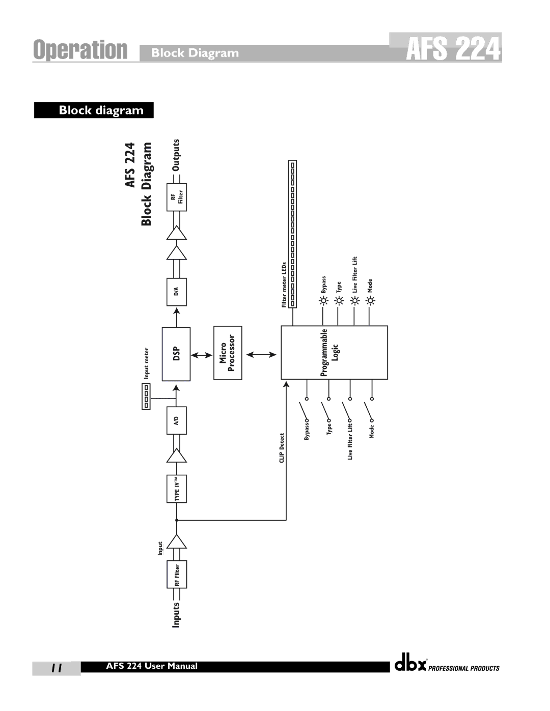
AFS 224 Block Diagram | Outputs | ||
|
|
| |
|
|
| |
RF Filter | |||
|
|
| |
|
|
|
|
D/A
|
|
|
|
meter | DSP | ||
Input |
|
| |
|
|
|
|
|
|
|
|
|
|
|
|
A/D
TYPE IV™
Input
Inputs RF Filter
Micro Processor
meter LEDs | Bypass | Type | Live Filter Lift | Mode |
Filter |
|
|
|
|
| Programmable | Logic | ||
|
|
|
|
|
|
|
|
|
|
CLIP Detect | Bypass | Type | Live Filter Lift | Mode |
®
11 | 386 UserAFSManual224 User Manual |
|
|
